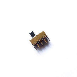
Cut about 3 mm of the toggle switch in order to fit it properly with the plastic switch of the Game Boy DMG.
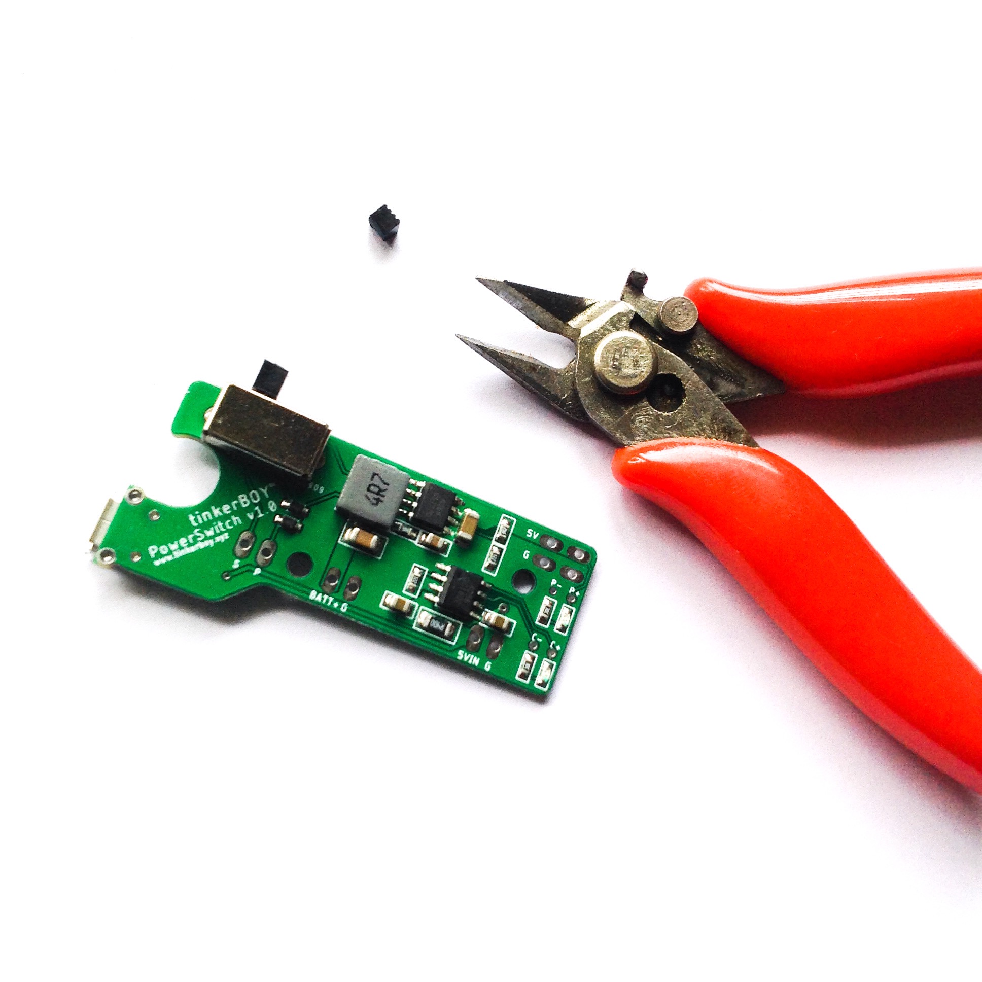
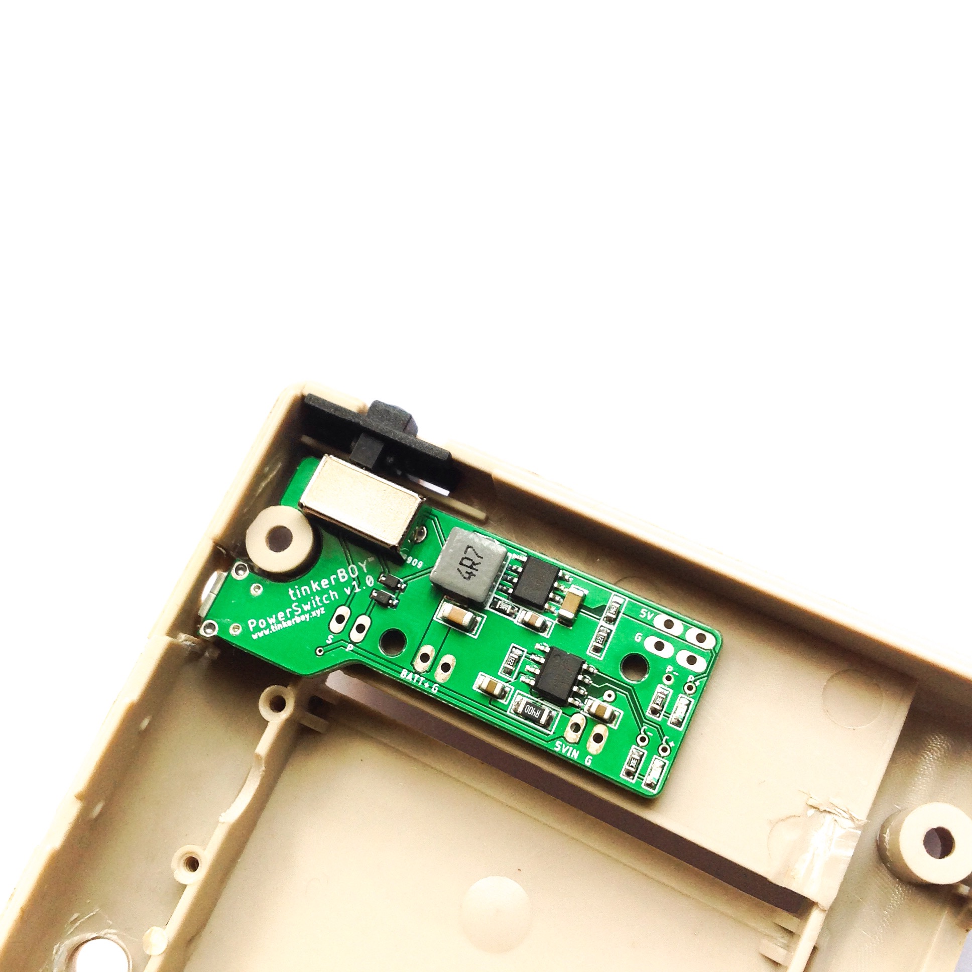
Cut about 3 mm of the toggle switch in order to fit it properly with the plastic switch of the Game Boy DMG.


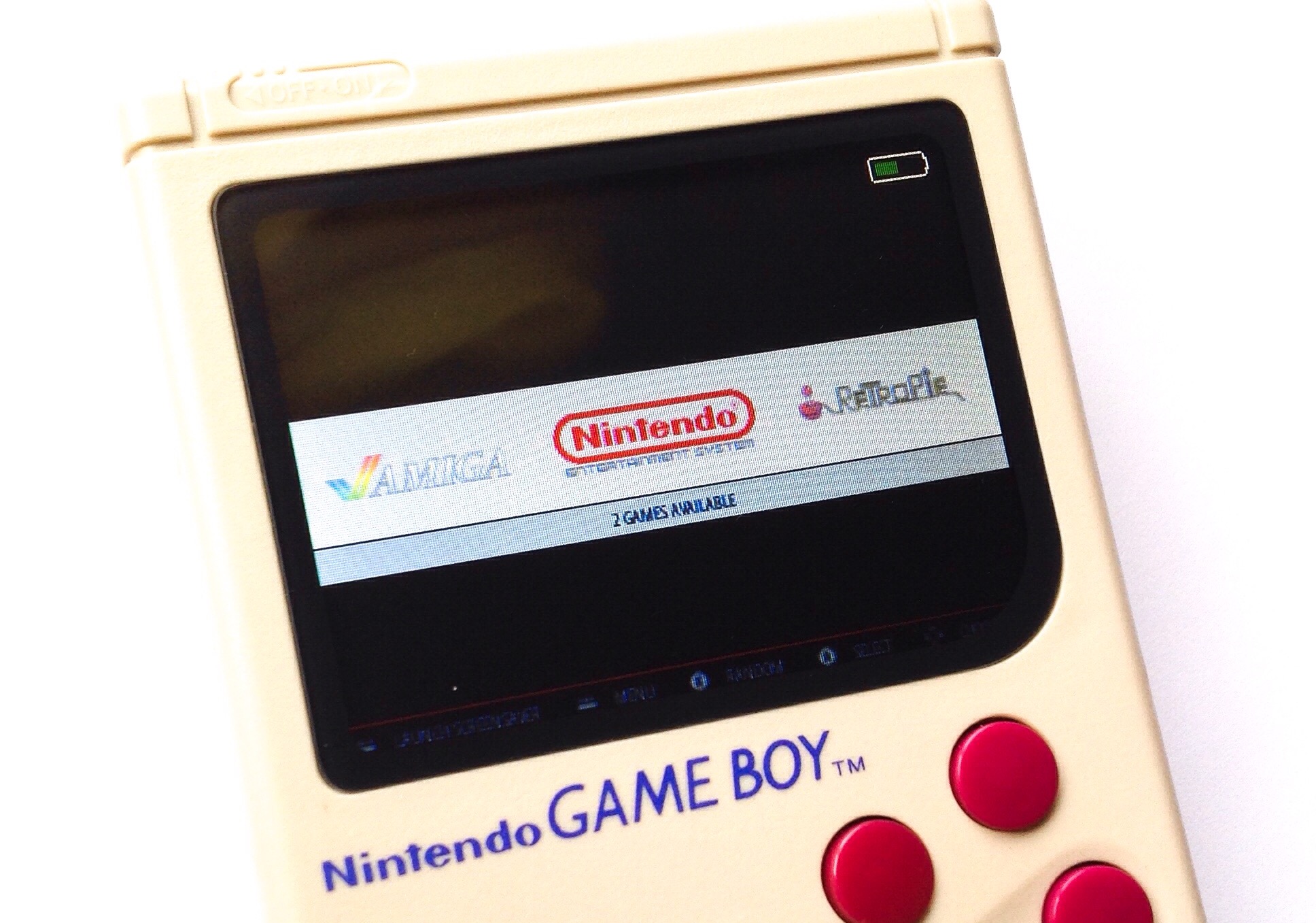
This tutorial is covers the steps on how to enable battery monitoring for the tinkerBOY Controller v3. Make sure your v3 is plugged in or connected to your Raspberry Pi before setting up the Battery Monitoring service.
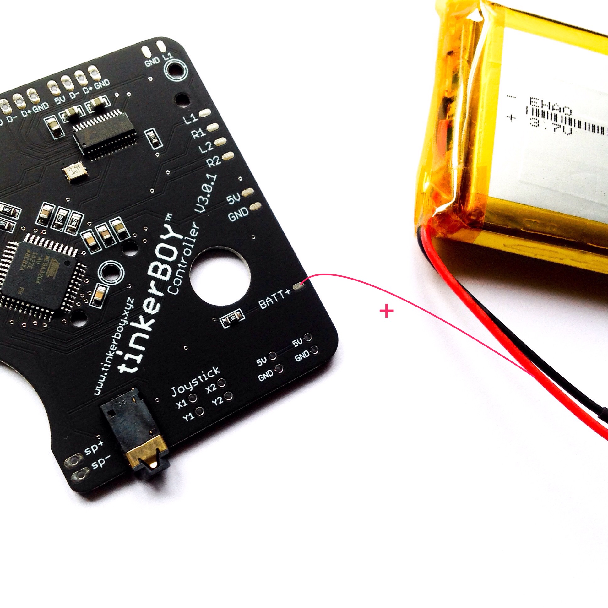
Solder a wire from the BATT+ pin on the v3 to the positive wire(red) of the battery.
Login to your Pi via SSH and type the following command:
wget -O - https://www.tinkerboy.xyz/setup.php -q | bash -s bm
It will install the necessary software for the battery monitoring service. It will also upgrade your v3’s firmware if needed.
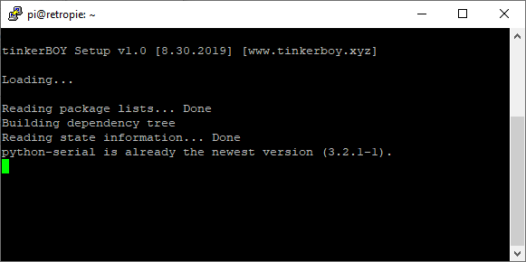
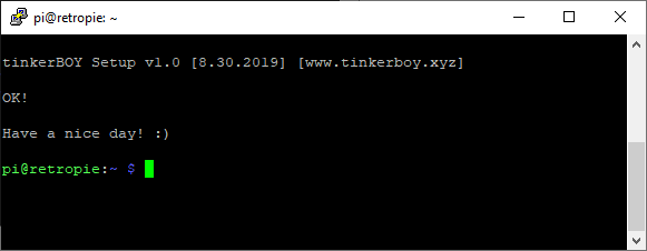
When it’s done you should get an “OK!” message if it’s successful. Otherwise, let me know when you get an error.
Type or copy paste the following commands:
sudo systemctl daemon-reloadsudo systemctl enable battmon.servicesudo systemctl start battmon.service
Issuing these commands will immediately start the Battery Monitoring service.
That’s it. Have a nice day! 🙂
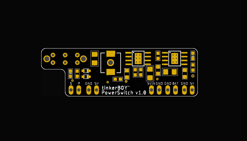
I’m currently working on a power board for Game Boy Zero which I will be calling the tinkerBOY PowerSwitch. It’s supposed to be a builtin upgrade for my tinkerBOY Controller v3.0 but I decided to design it separately and integrate a slide switch. This way, it’s not limited to just my v3 but can be used by anyone using any controller board as well as my other controllers like the v1.1, v1.2, v2.0.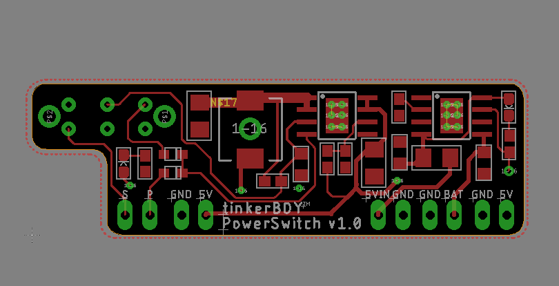
The 3 most important features will be 5V boost, battery charger, and a safe shutdown feature. I’m almost done with the design and I will be ordering some PBCs soon so I can test it. So don’t forget to subscribe to my facebook page at https://www.facebook.com/tinkerBOY/ for updates.
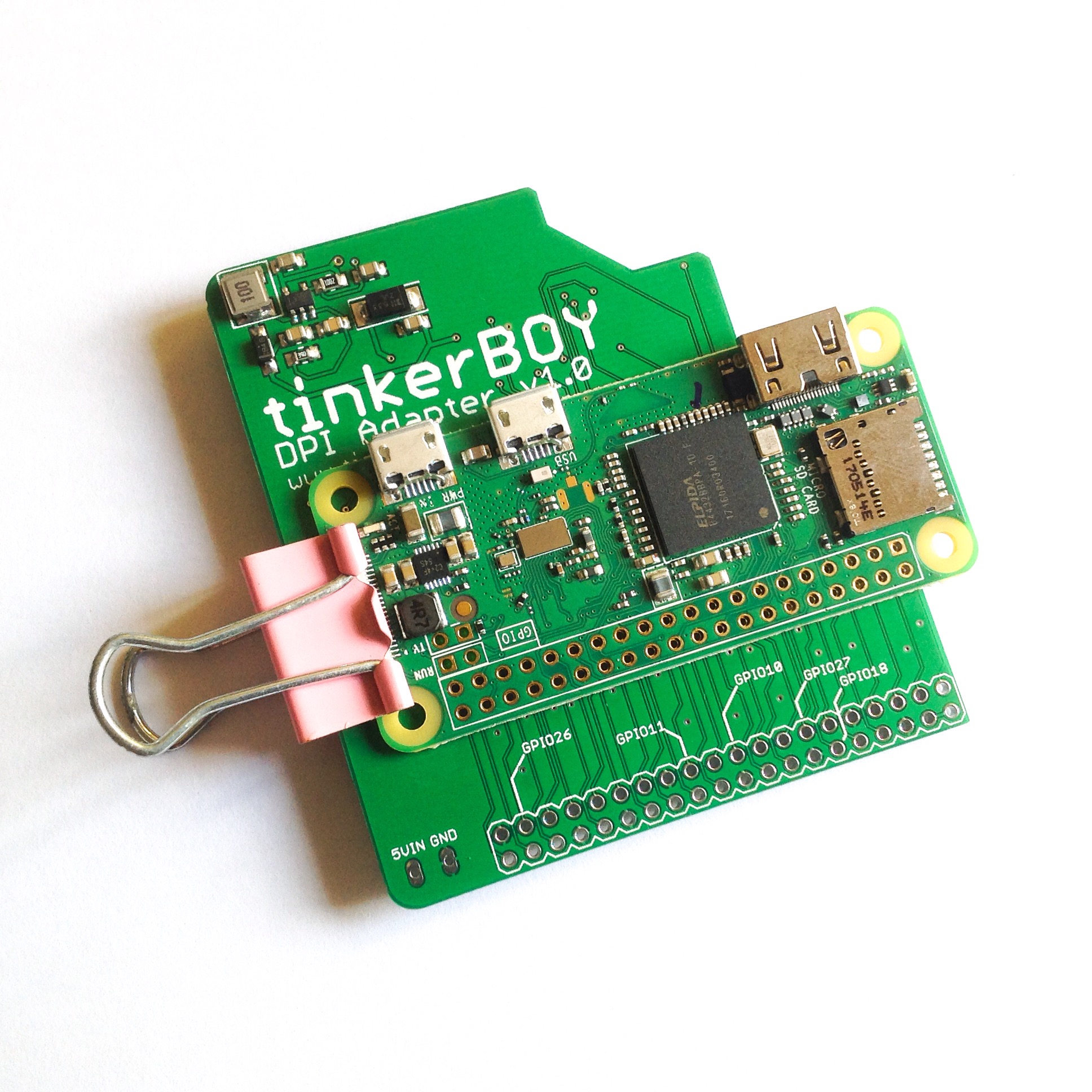
This method does not use a 40-pin header pins but it’s easier. Place the Pi Zero on top of the DPI Adapter and align the holes. Use a binder clip to hold them together.
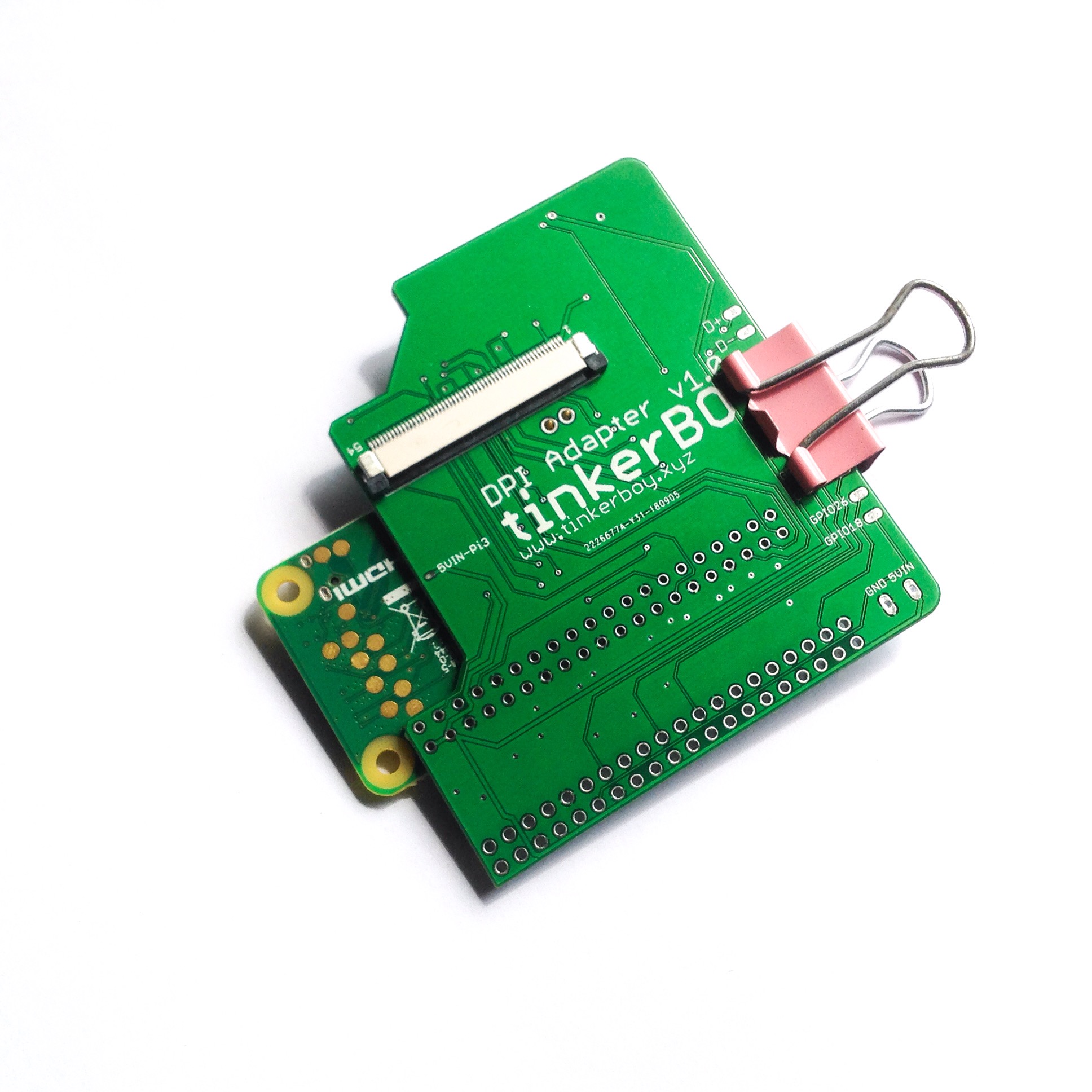
Now, start soldering each of the Pi Zero’s GPIO holes making sure there’s a proper contact to each of the holes on the DPI Adapter.
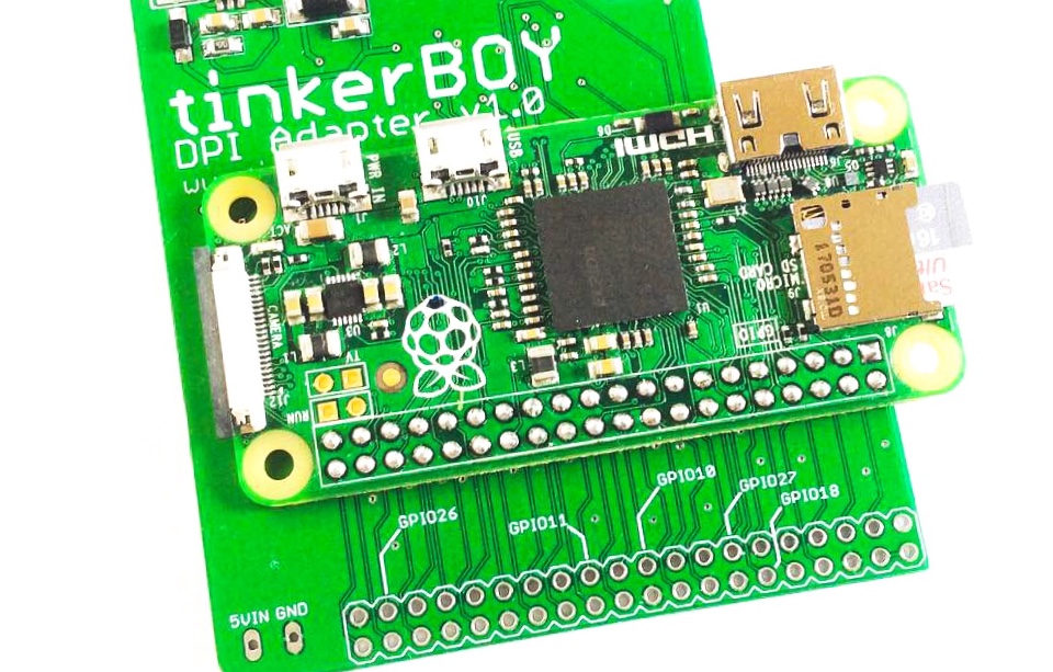
You can also solder from the bottom just to make sure each holes are soldered properly.
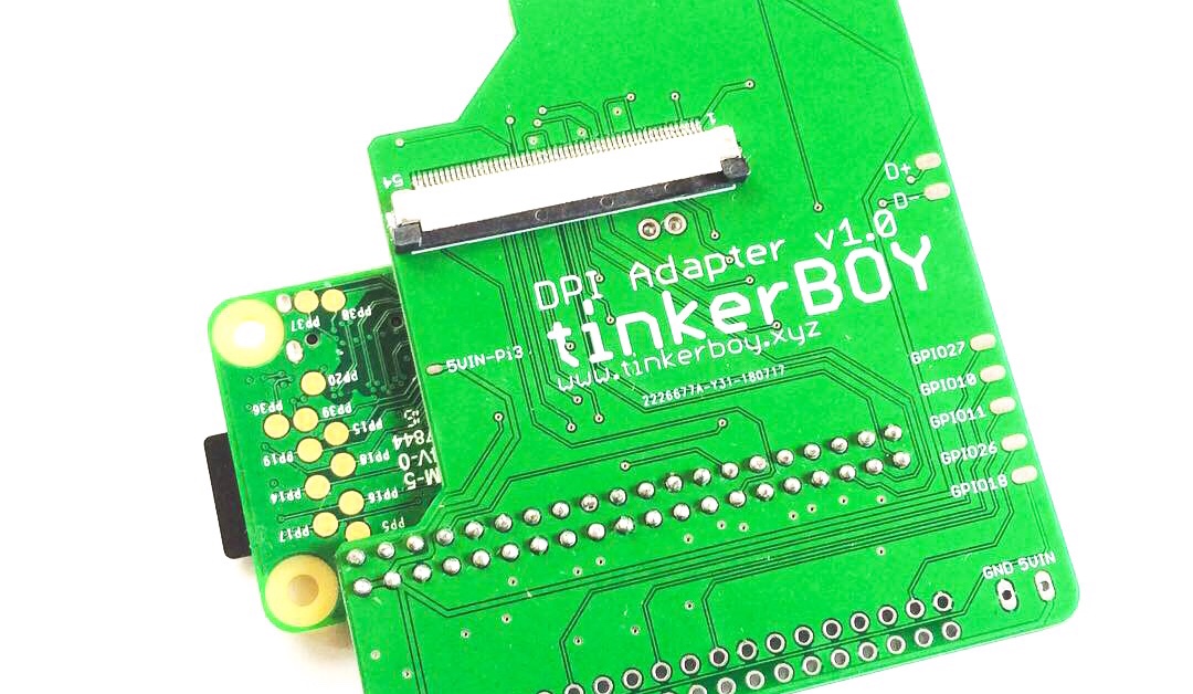
The final step is to solder the Pi Zero’s USB data pins (D+ and D-) to the 2 holes on the DPI Adapter. These holes will connect the Pi Zero’s data pins to the D+ and D- pads on the adapter for connecting any USB device. (Note: The D+ and D- pads on the DPI board V1.0 are mislabeled. The upper pad should be D- and the lower pad should be D+. Thanks to Paul for reporting.)
UPDATE: The D+ and D- data pins are now correctly labeled on v1.1 and moved to front left of the board just above the 5v and GND pin holes.
The 5VIN and GND pin holes below the tinkerBOY DPI Adapter are your 5v and GND inputs.
Start by placing the header pins in to the pin holes designed for the Pi Zero:
And mount the Pi Zero this way: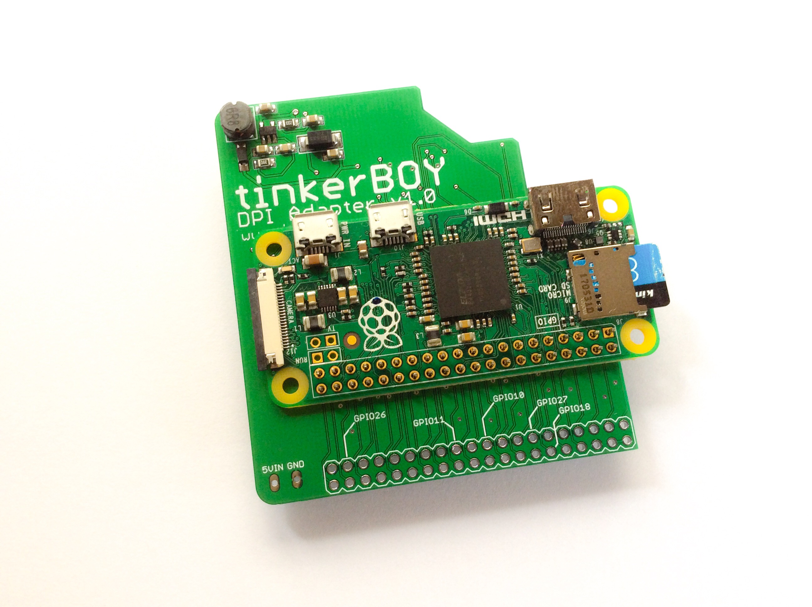
It’s recommended to put a kapton tape or anything in between the adapter and pi zero to avoid shorts before soldering the header pins to the Pi.
The next step is to cut the pins and plastic below the header pins and solder them to the DPI Adapter.
The final step is to solder the Pi Zero’s USB data pins (D+ and D-) to the 2 holes on the DPI Adapter. These holes will connect the Pi Zero’s data pins to the D+ and D- pads on the adapter for connecting any USB device. (Note: The D+ and D- pads on the DPI board are mislabeled. The upper pad should be D- and the lower pad should be D+. Thanks to Paul for reporting.)
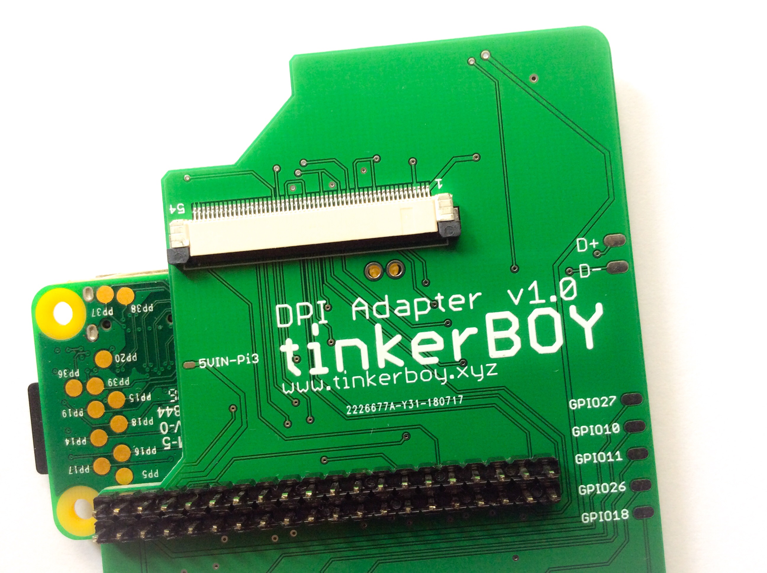
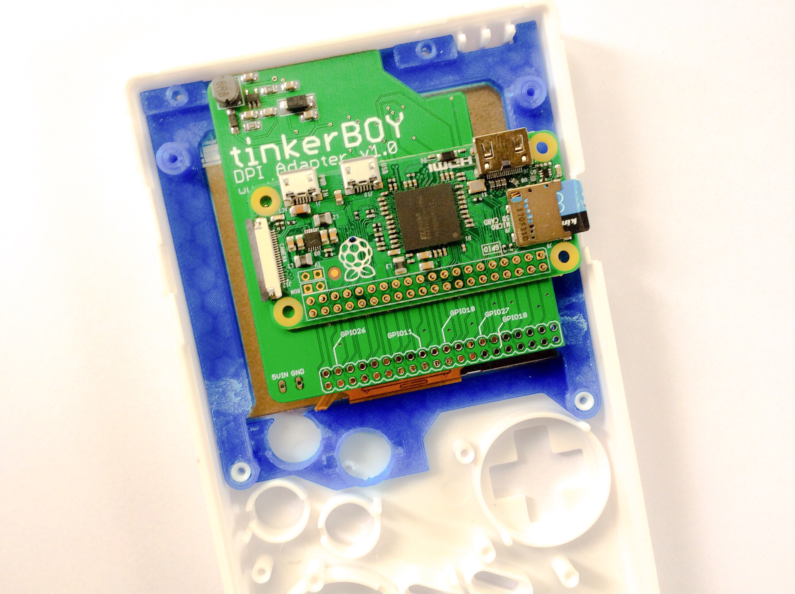
The 5VIN and GND pin holes below the tinkerBOY DPI Adapter are your 5v and GND inputs.
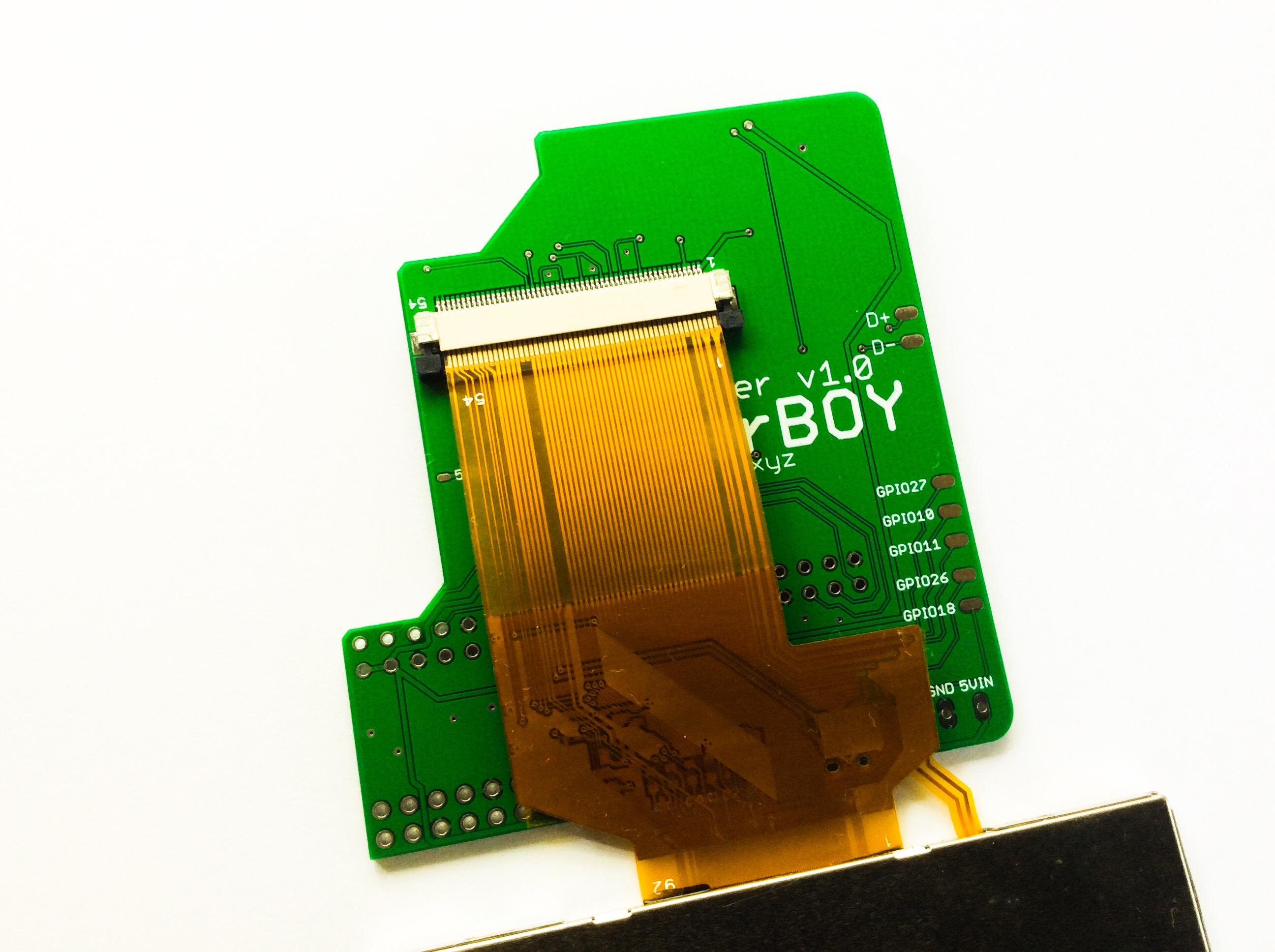
The DPI Adapter uses a 54-pin Top Contact FPC Connector for the 3.5″ LQ035NC111 LCD. When you insert the LCD’s ribbon cable make sure the contact pins are facing upwards.
I get a lot of wiring inquiries about the 3.5″ GearBest Screen so I decided to make one.
Most of these 3.5″ screens are intended for 12v power supply. The 12V input goes to a chip called XL1509 and converts that to 5V. Like any DC to DC converter there’s always going to be wasted power as a result of the conversion. This is the reason why I highly recommend that you do the 5v mod eventhough the screen works if you feed it with 5v without the need for any modification.
To make the connections more reliable let’s remove the Female JST connector..
..just be careful not to lift the contact pads which I’ve mistakenly done here. Luckily the board has two video connections which are AV1 and AV2. I will be using the AV1.
Cut the cable that came with it and solder the wires directly to the board. In order to do the 5V mod, you just solder the RED wire directly to the XL1509’s Pin 2 or to the SS24’s cathode pin which is easier to solder to. The other end of the RED wire goes to your 5v power supply of course (PowerBoost 5v output). Since the Raspberry Pi only requires just one video connection, solder the YELLOW wire to the Pi’s TV connection. Join the WHITE and BLACK wire and solder them directly to the GND pad on the screen board. The WHITE(GNDTV) wire goes to the GND beside the TV pin on the Pi while the BLACK wire goes to your normal powerboost’s GND output.
Yep, That’s it!
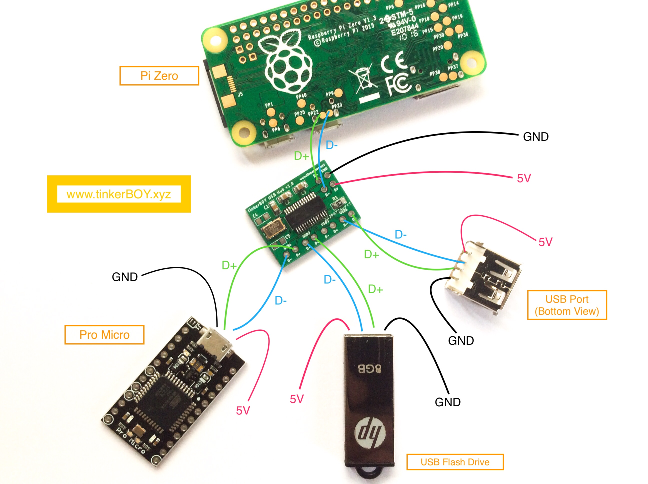
Pi Zero:
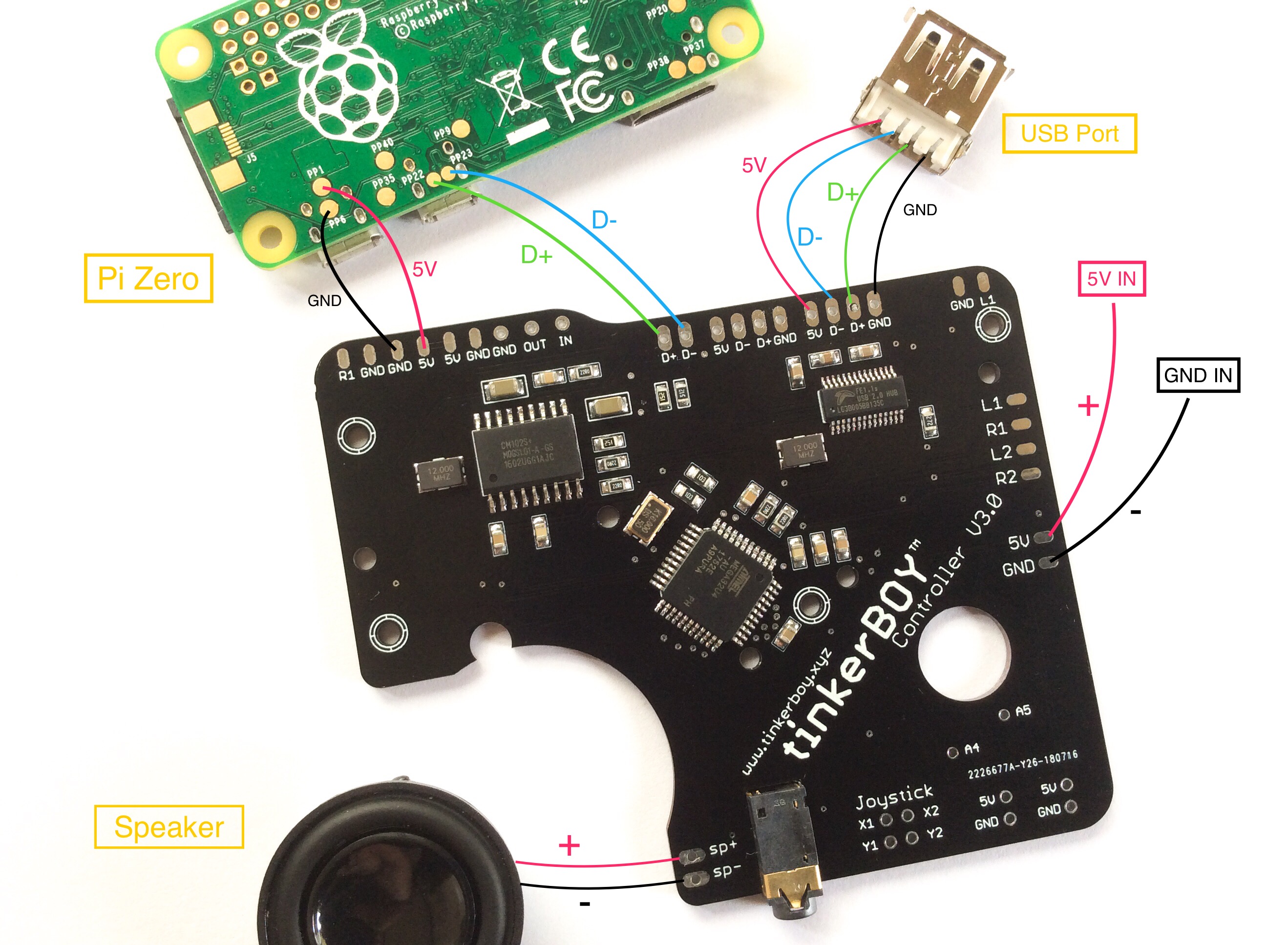
For the Pi 3 just wire the data pins to the corresponding pins on the v3 controller board. Here’s how you power the Pi 3.
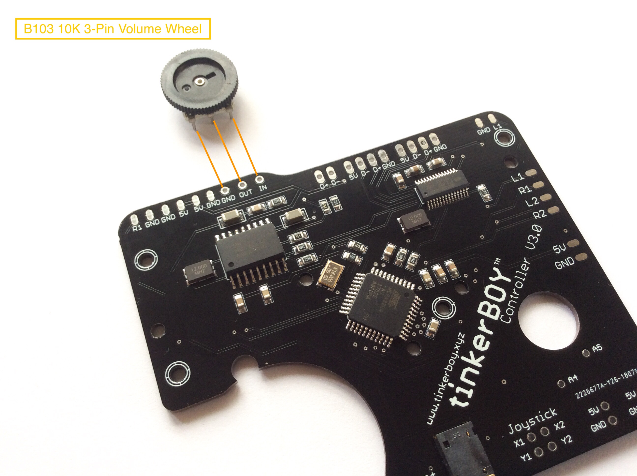
Before you wire a 3-pin volume wheel make sure you disable the “Digital Volume” setting on your tinkerBOY Controller v3.0.
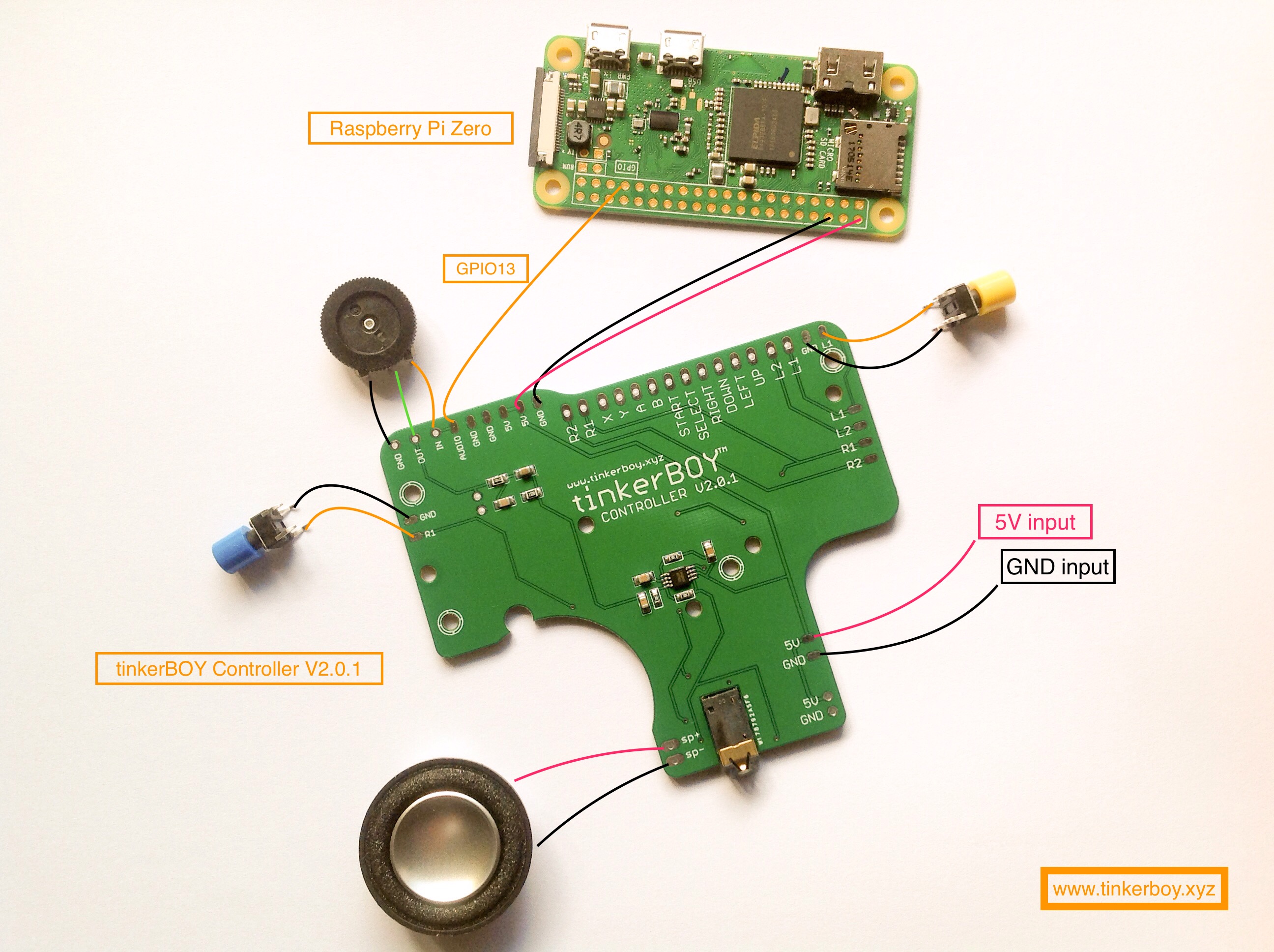
Use the diagram below to wire the tactile switches for the L and R shoulder buttons. You can wire the GND to any GND pins on the board or any GND somewhere else like from the Raspberry Pi, Battery, powerboost, etc…
For v3.0: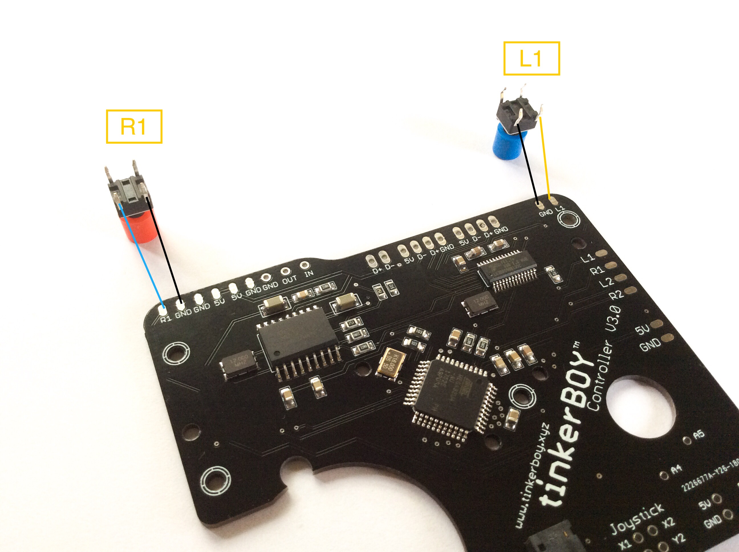
For v1.1, v1.2, v2.1, and v2.2:
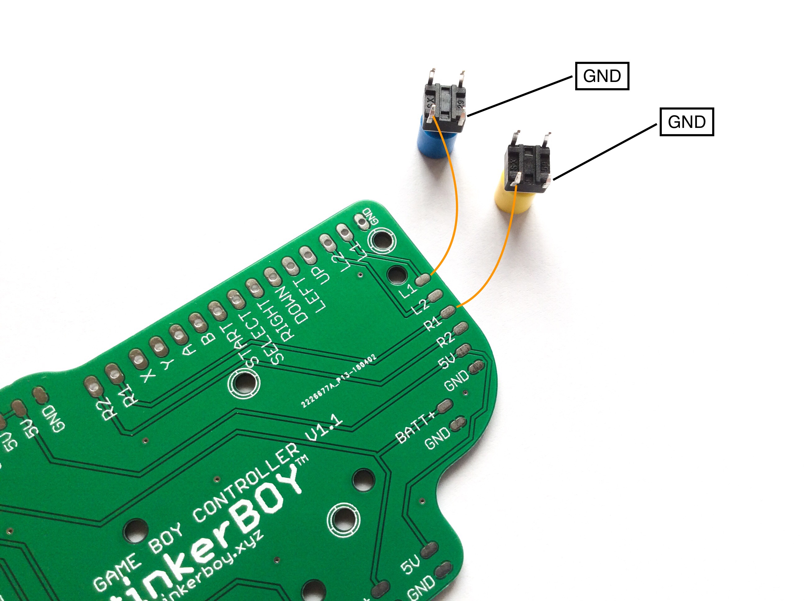
Just do the same wiring if you want to add the L2 and R2 buttons.
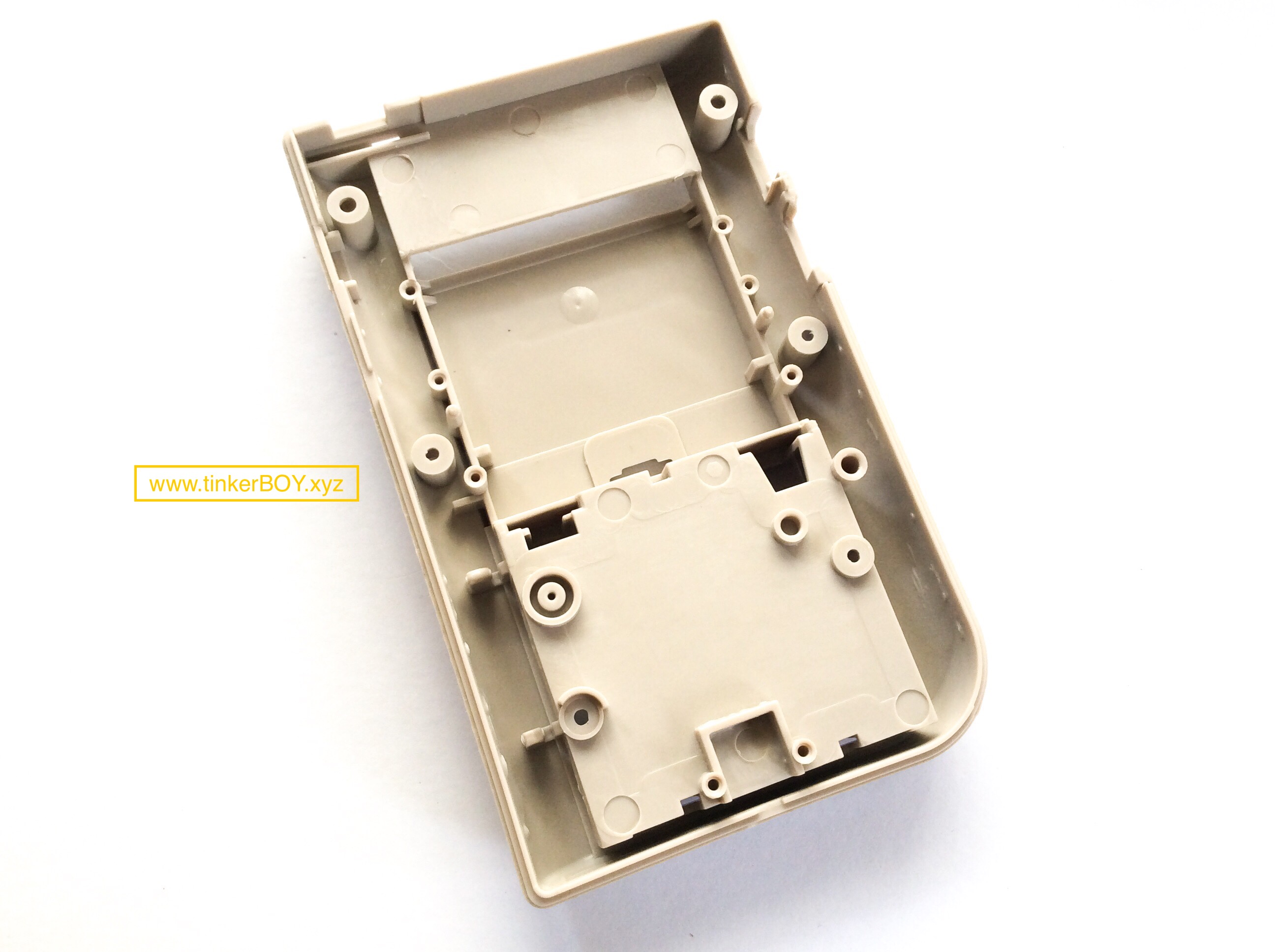
Minimal back case mod for tinkerBOY Controller v2.1 or v2.2:
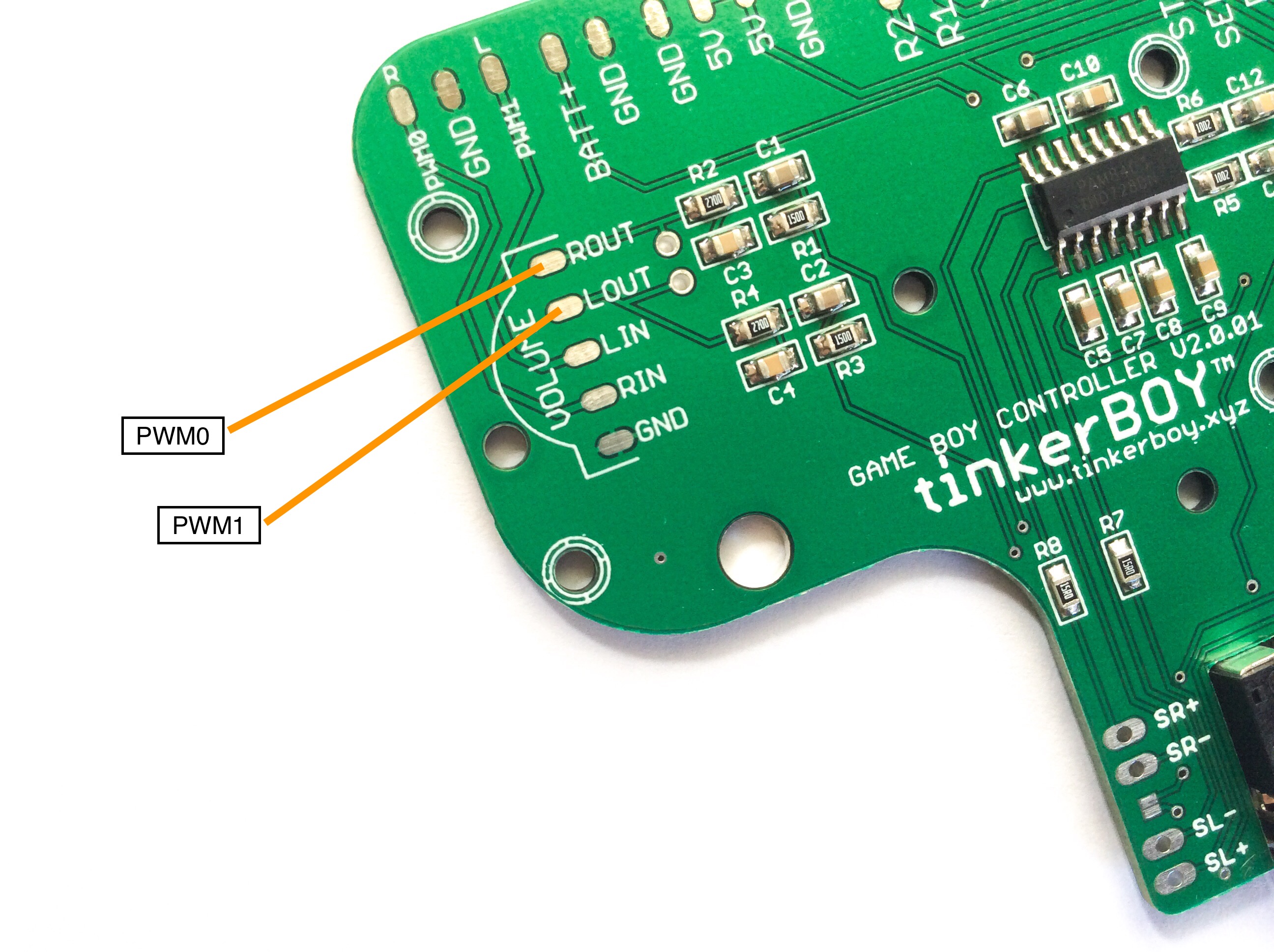
If you want to bypass the volume wheel or just want to control the volume by other means, here’s how to do it:
Update: tinkerBOY DPI Adapter v1.0 now available!
I finally had time to populate and test my DPI adapter prototype which will be included as part of my all-in-one board for Game Boy Zero / 3. So far it’s working fine. The DPI screen looks way better than composite.
I actually built a Game Boy 3 using just a simple FPC breakout board for doing the DPI connections but it was very difficult to make it work. Obviously because of all the wires I soldered to the Pi which are prone to interference. But I managed to make it work anyway. So I made a prototype to make it easier to use a DPI screen.
The AIO board will be compatible with Raspberry Pi Zero and Pi 3. Both will have sdcard access from the “CONTRAST” area of the Game Boy case.
Adding a separate GND wire for the video (yellow wire) is optional but recommended. Diagram assumes you are using a screen that works on 5V power like the GearBest Screen.
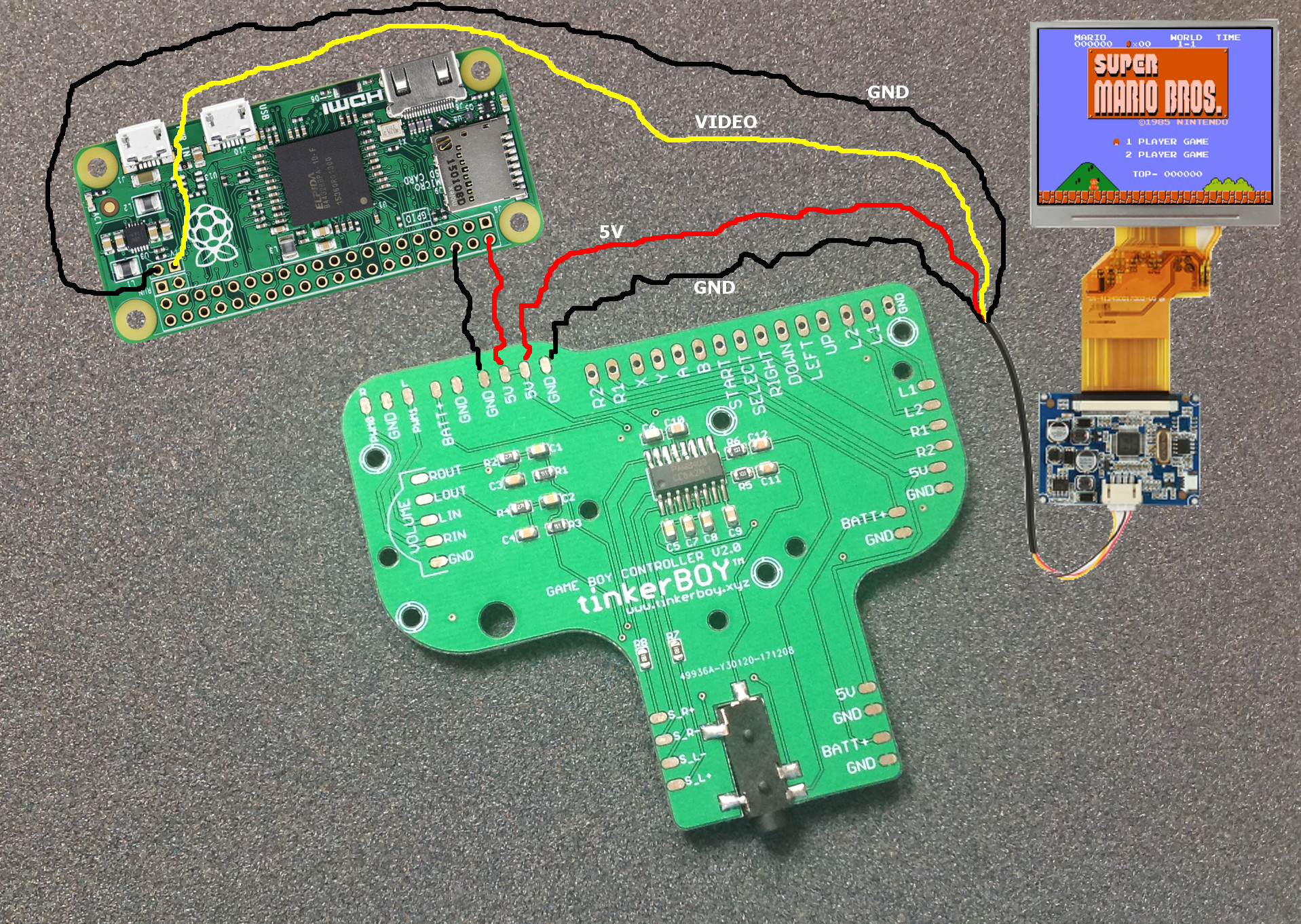
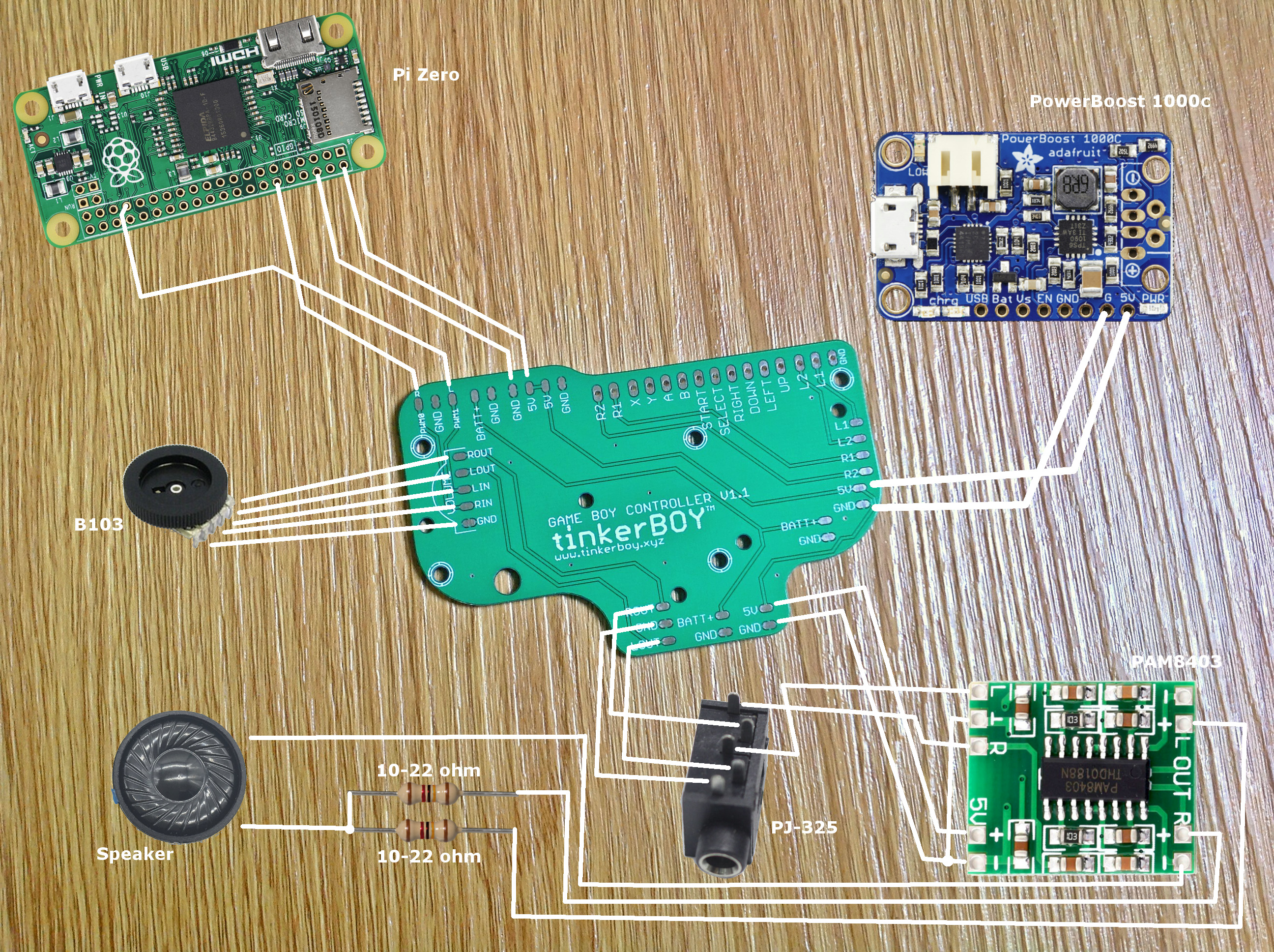
The pwm audio on the Pi Zero is horrible and noisy so you probably be needing a low/high pass filter too.
For the controllers, you can visit GPIO Button Guide for Game Boy Controller v2.0 / v2.1.
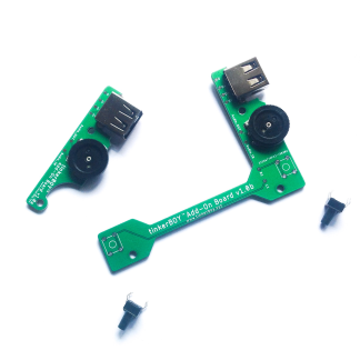
Wiring the Game Boy Controller v2.0 to the Pi Zero’s GPIO pins is the simplest way to configure controller inputs for the Game Boy Zero without any additional component. You can use the following diagram to solder the button inputs to the Pi.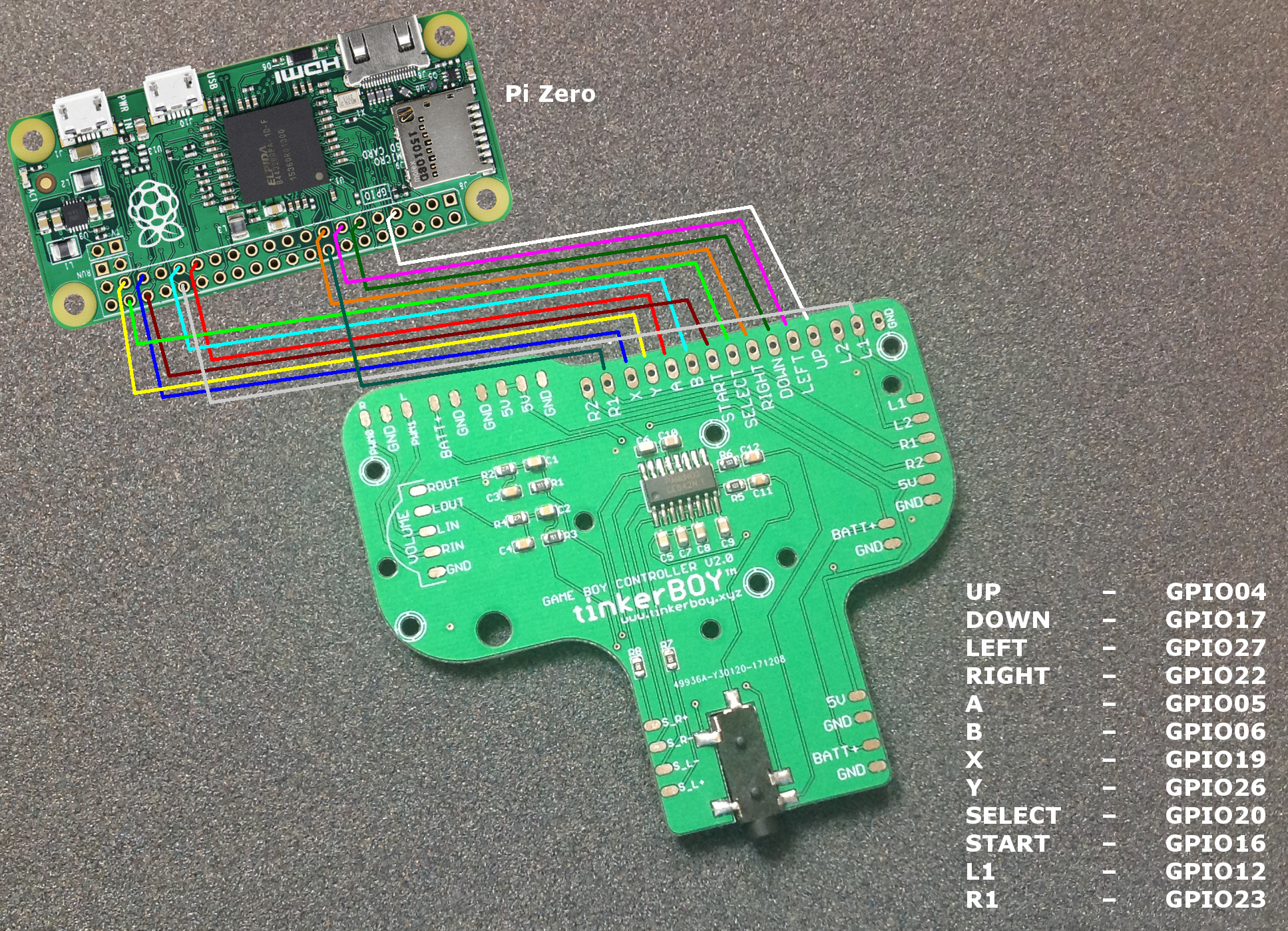
I got asked a few times about the difference of each of the 3 Game Boy Controllers I currently sell so I’ll try my best to explain it here. I’m talking about my Game Boy Controller v1.1, Game Boy Controller 2.0, and Game Boy Controller v2.1.
This is one of the first boards I designed while learning Eagle software and electronics. Most of the boards that were available when I started building Game Boy Zero were not really solder-friendly and were just plain sim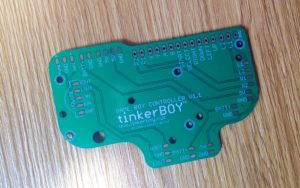 ple PCB with only solder pads for the controller buttons. So I designed one in order to make it easier to solder and included some useful features like builtin power strips, audio and volume wheel solder pads which is inspired by Helder‘s work. I think got the idea of building one from rolf.
So what does it do? Just like any simple Game Boy Common Ground PCB it just does one thing and that is to provide controller/button inputs for the Game Boy Zero only. Although I made my v1.1 a little easier on the soldering side and added some useful features I mentioned above. But of course you need more than a simple pcb to build a proper working Game Boy Zero. Aside from the Game Boy case, screen, battery, Pi Zero, 5v boost and charger module, you also need an audio amp, speaker, a low/high pass filter, headphone jack, etc..
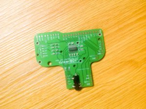
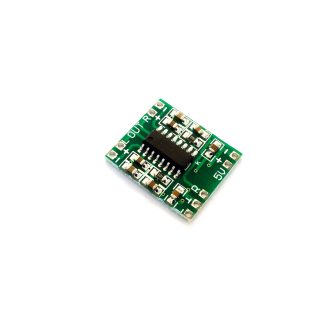
I have built and sold a lot of GBZs and GB3s here in the Philippines using just a simple PCB button which requires a lot of work and soldering because there wasn’t much available option. So I decided to make my own. Here comes my Game Boy Controller v2.0 which includes the low/high pass filter, PAM8403 audio amp, and a headphone jack already builtin to it. It’s similar to Helder’s Audio Board which I got the inspiration from and since the schematics for the PAM8403 and the low/pass filter are easily obtainable.
So what’s the advantage over the v1.1? It may seem simple to build, but soldering and wiring a separate audio amp, low/high pass filter, headpone jack, and the volume wheel is pretty confusing to most and requires some basic electronics and troubleshooting skill. The v2.0 should save you time from figuring out and soldering the audio part of a Game Boy Zero build.
Another important advantage is it’s simplicity. It does not use any USB device for the audio and controllers so you get to keep the only USB port on a Pi Zero for external use. This is not an issue with a Pi 3 build since it has plenty of USB ports. Which lead me to my next board.

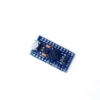
My Game Boy Controller v2.1 has all the builtin features of my v2.0 board but instead of using the Pi’s GPIO pins, it uses a USB-based Arduino Pro Micro module for the controllers which practically reduces the number of wires to solder. You only need to solder 2 connection wires while my v2.0 and v1.1 board need atleast 10 button connections excluding the L and Rs.
Another advantage is the Analog Stick support which you cannot do on a v1.1 or v2.0 board without buying a separate Pro Micro or a Teensy module. While it’s perfect for Pi3 builds, it takes away the only usb port on a Pi Zero unless you consider an external usb hub for it. Which again lead me to my next board.
I’m still working on this one. 🙂 Features should include a builtin USB audio, amp, atmega32u4, etc.
So, that’s it for now. I hope you found this information helpful in building your own Game Boy Zero. Please don’t hesitate to contact me for any help or advice.