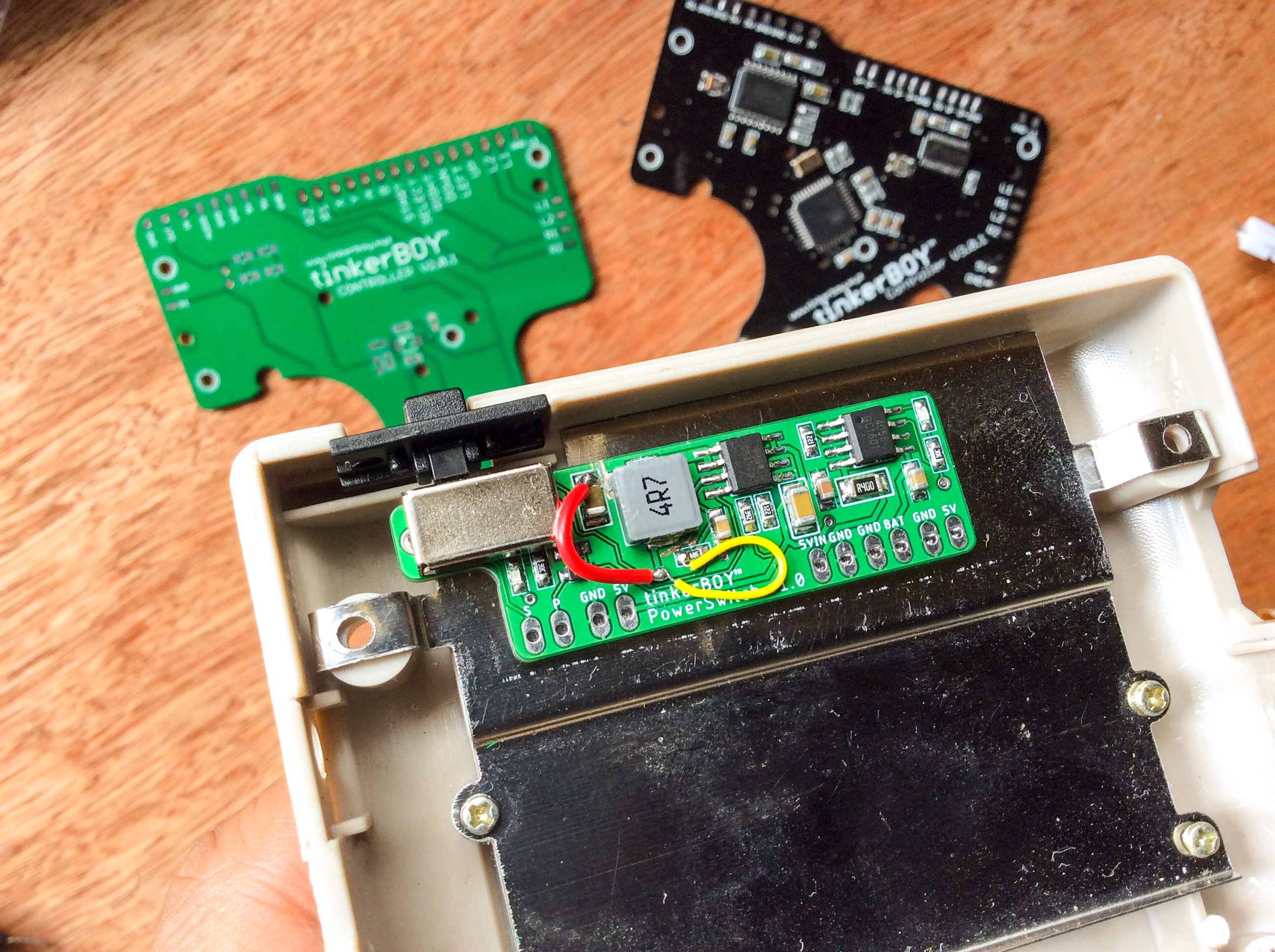
Cut about 3 mm of the toggle switch in order to fit it properly with the plastic switch of the Game Boy DMG.
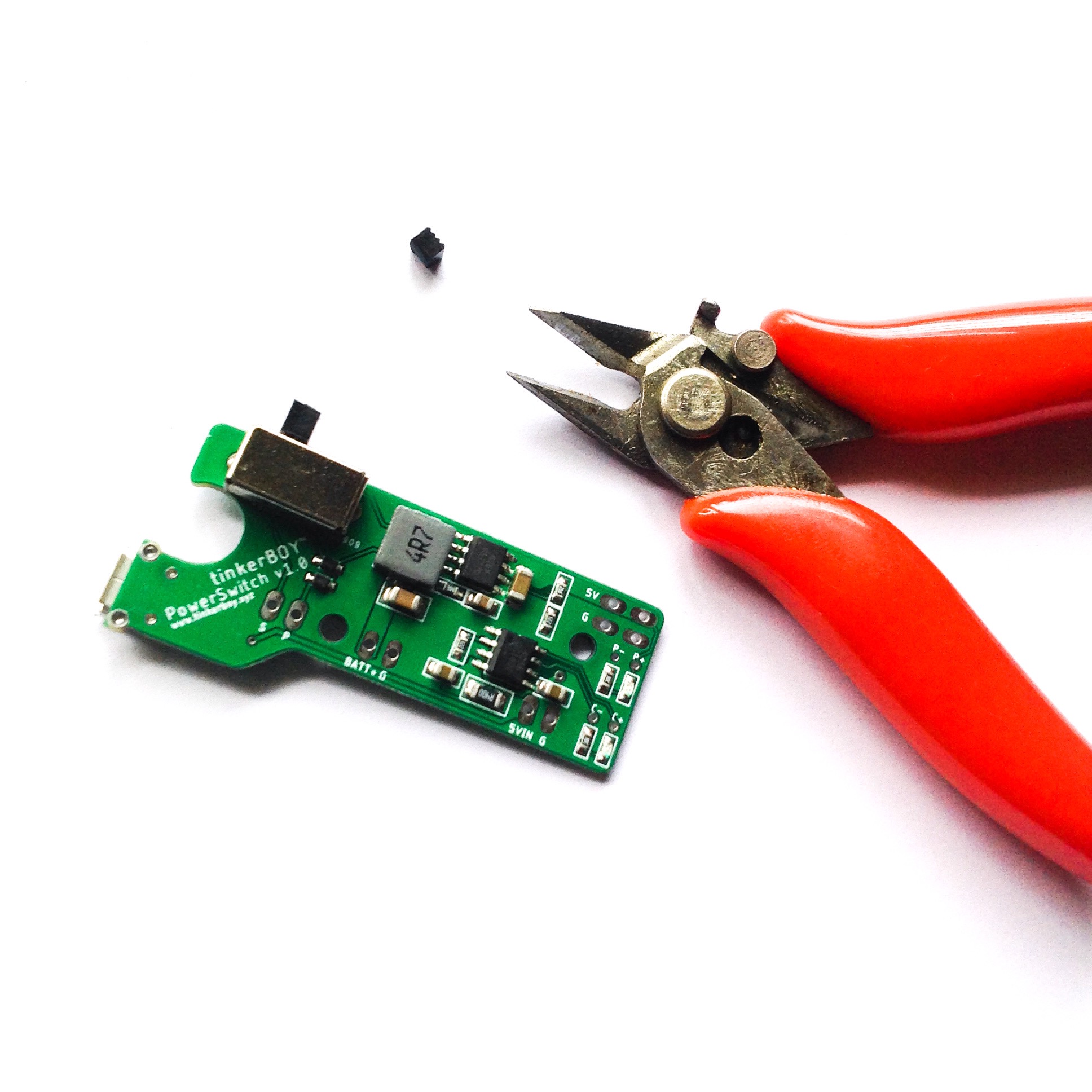
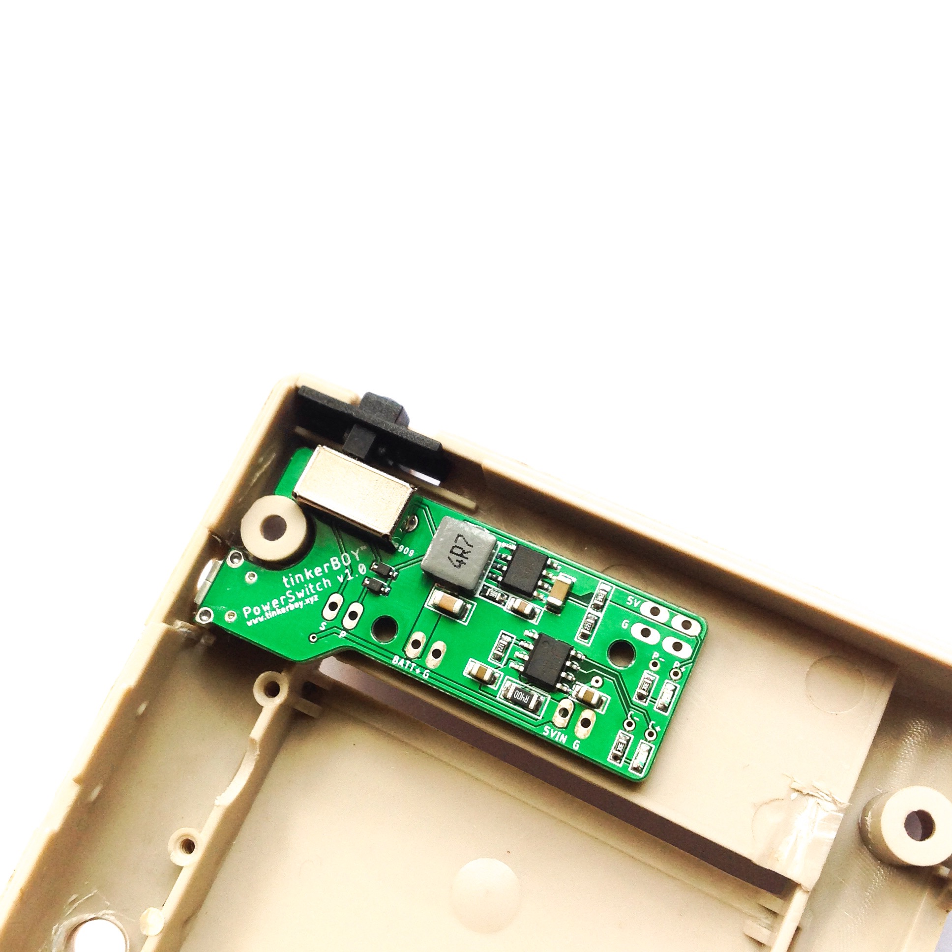
Cut about 3 mm of the toggle switch in order to fit it properly with the plastic switch of the Game Boy DMG.
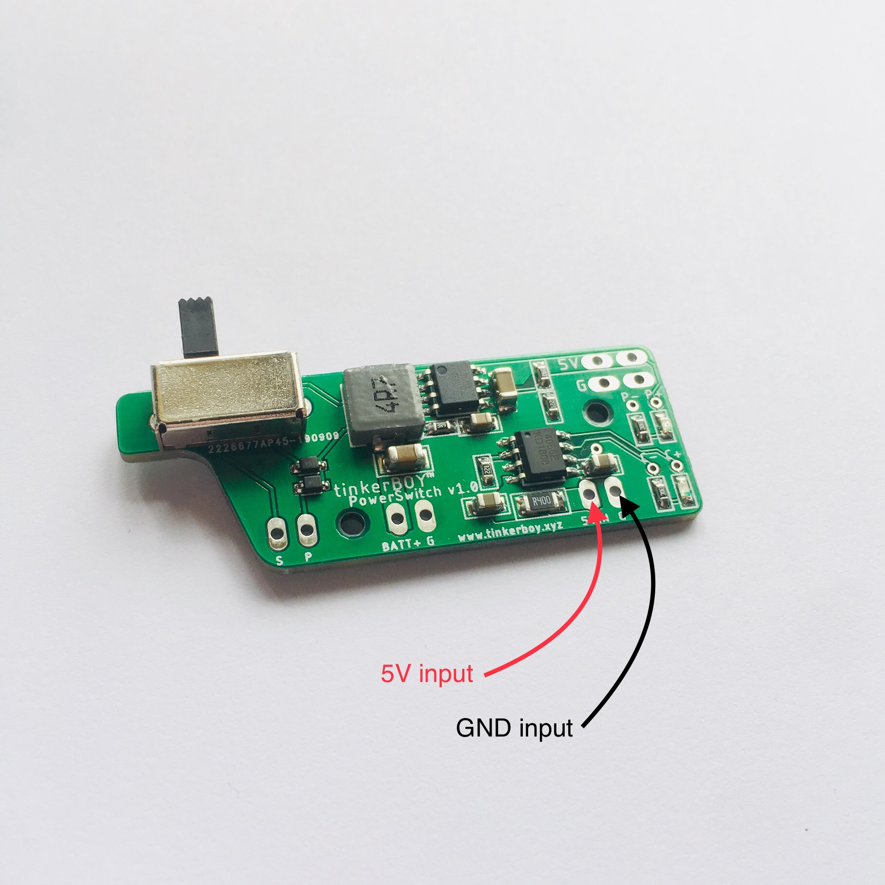
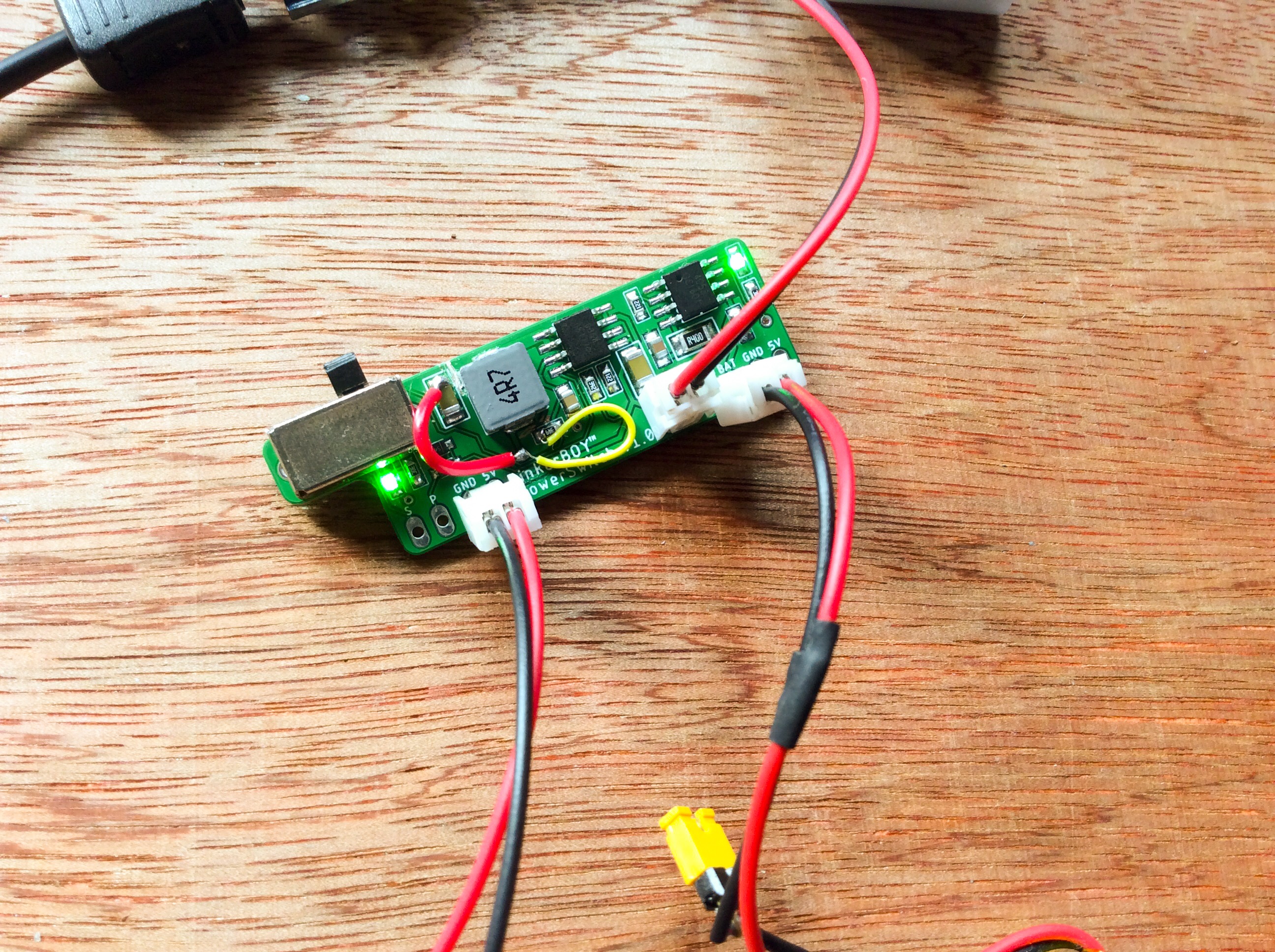
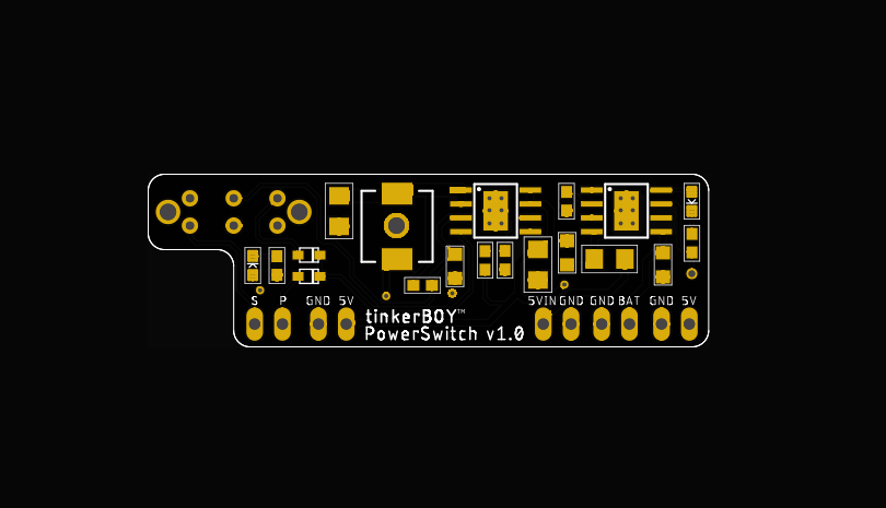
The BATT+ and G pins are the inputs for the battery. BATT+ goes to your battery’s positive wire (Red) while G goes to GND wire (Black).
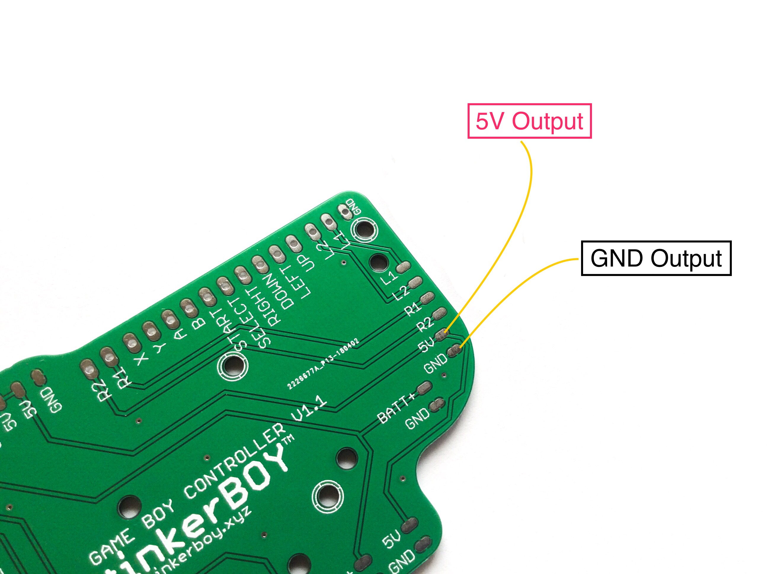
The 5V and G pins are obviously the PowerSwitch’s 5V+ and GND outputs.
TheS and P pins are your Safe Shutdown GPIO pins. The S pin goes to GPIO11 and P goes to GPIO10 on the Raspberry Pi.
Power On LED – Use the P- and P+ pins for connecting external LED as power on indicator. P- is cathode(-) and P+ is the anode(+). Use a resistor in series with P-.
Charging LED – Use the C- and C+ pins for connecting external LED as charging indicator. C- is cathode(-) and C+ is the anode(+). Use a resistor in series with C-.
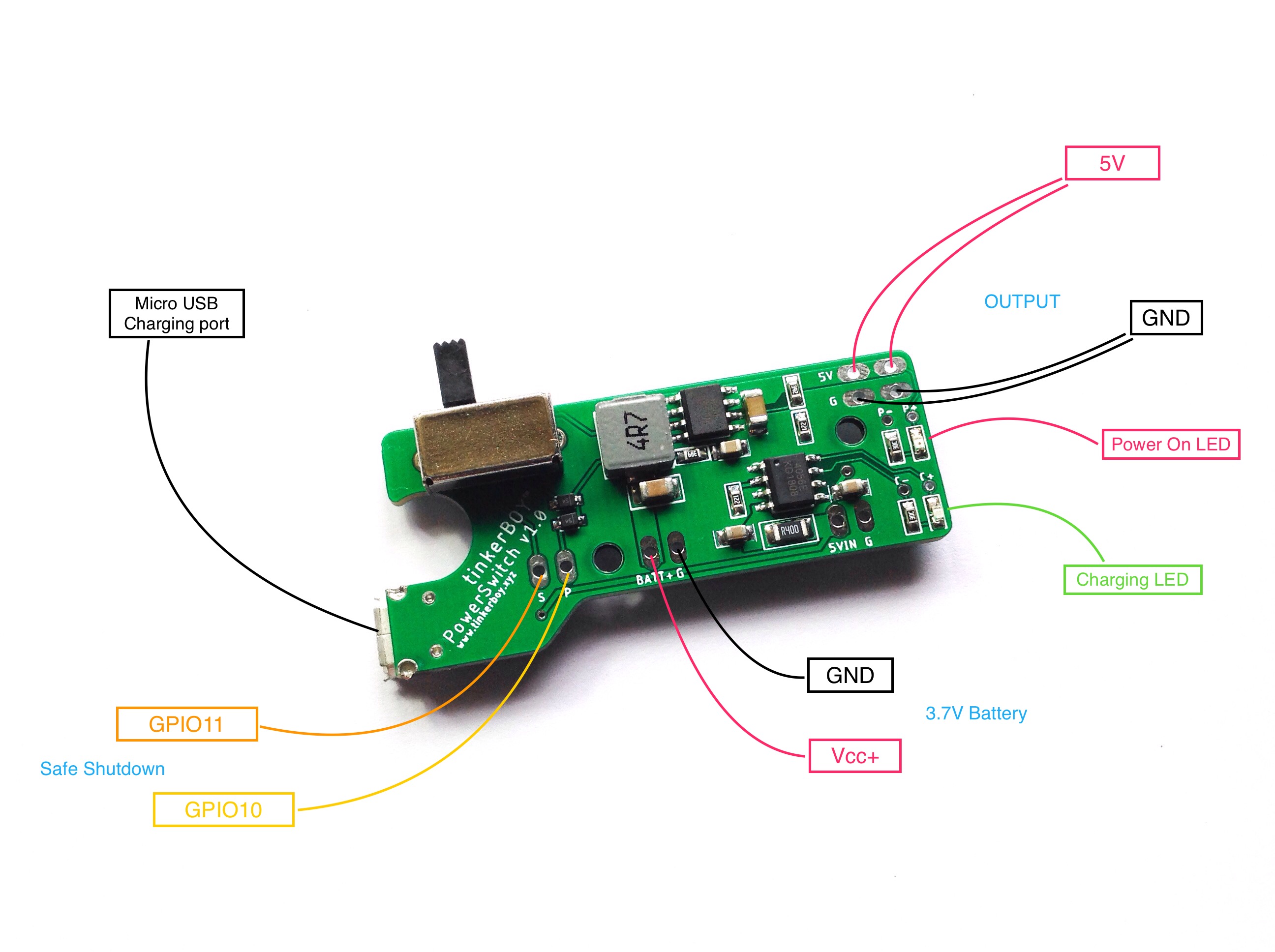
If you want to use your own charging port like a dc barrel jack or usb type-c port, you can use the 5V input and GND input for the PowerSwitch without charging port.
In order to enable the Safe Shutdown feature of the PowerSwitch, login via SSH and execute the following command:
wget -O - https://www.tinkerboy.xyz/setup.php -q | bash -s ss
When it’s done you should get an “OK!” message if it’s successful. Otherwise, let me know when you get an error.
Now restart your Pi by issuing sudo reboot. That’s it!
Have a nice day! 🙂
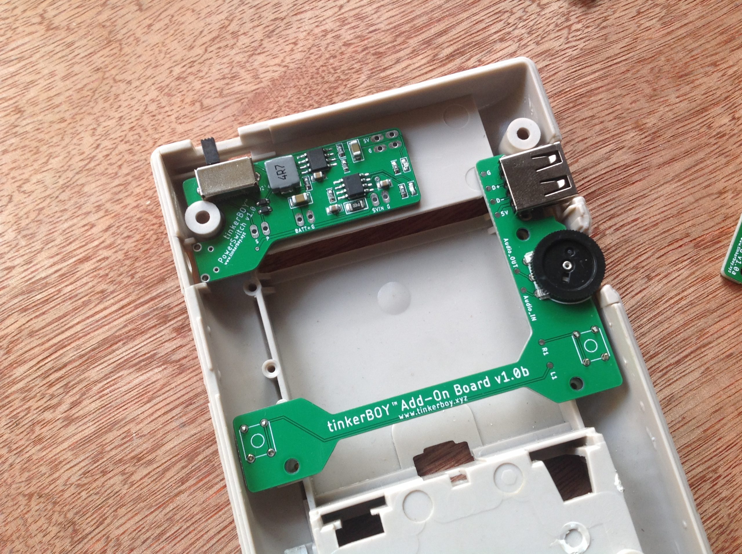
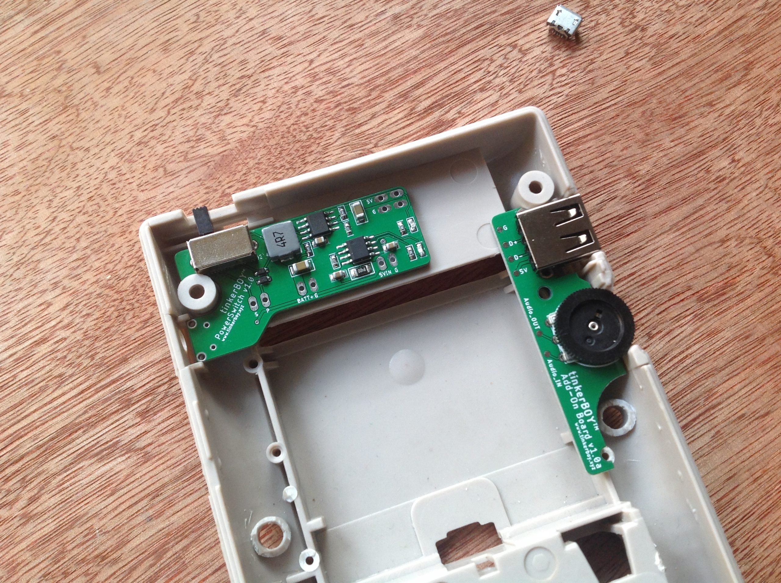
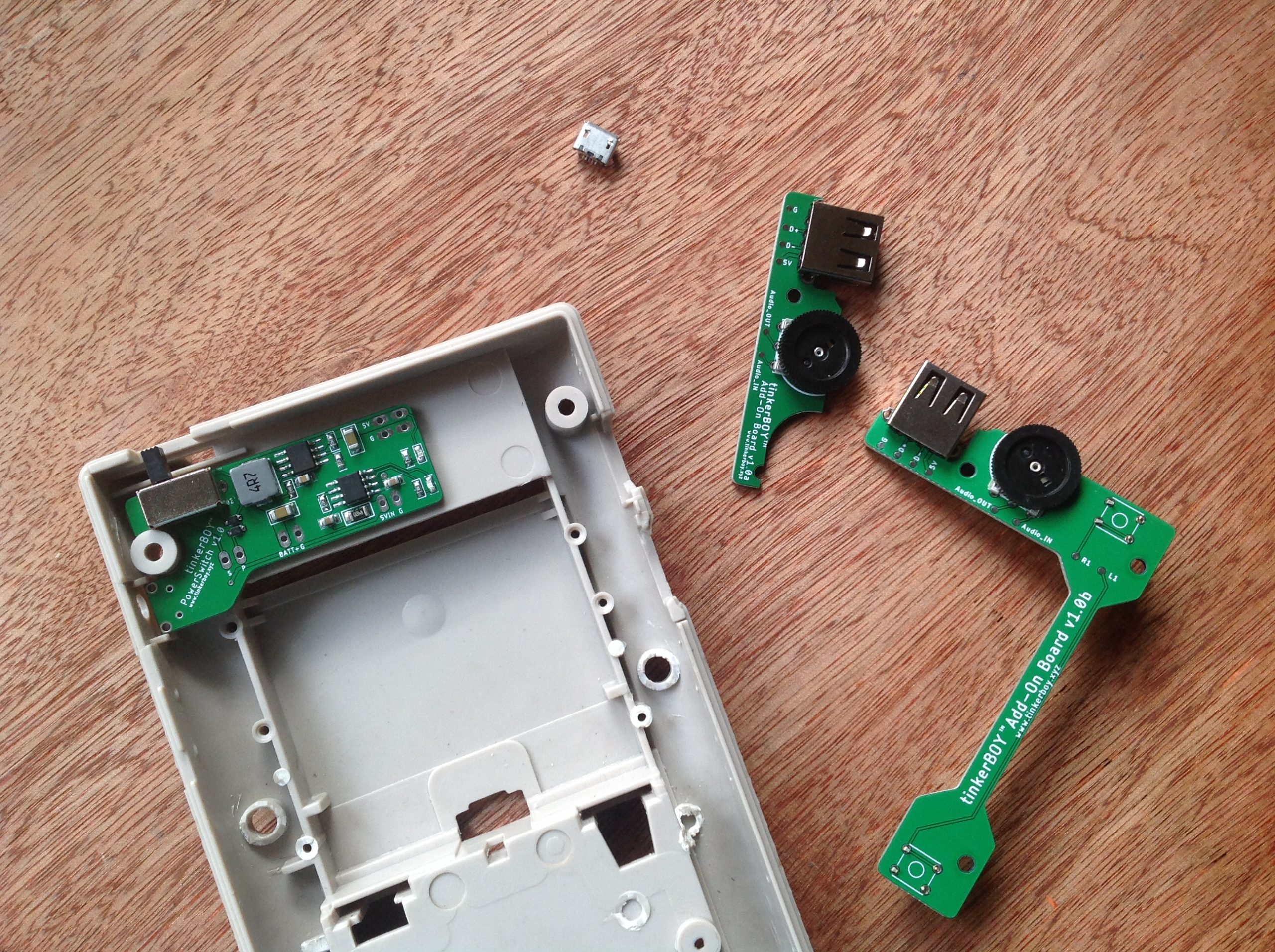
With the issues on the prototype #1 I revised the PowerSwitch and included a microusb port for charging. My initial testing is looking good on both the boost and charging part.
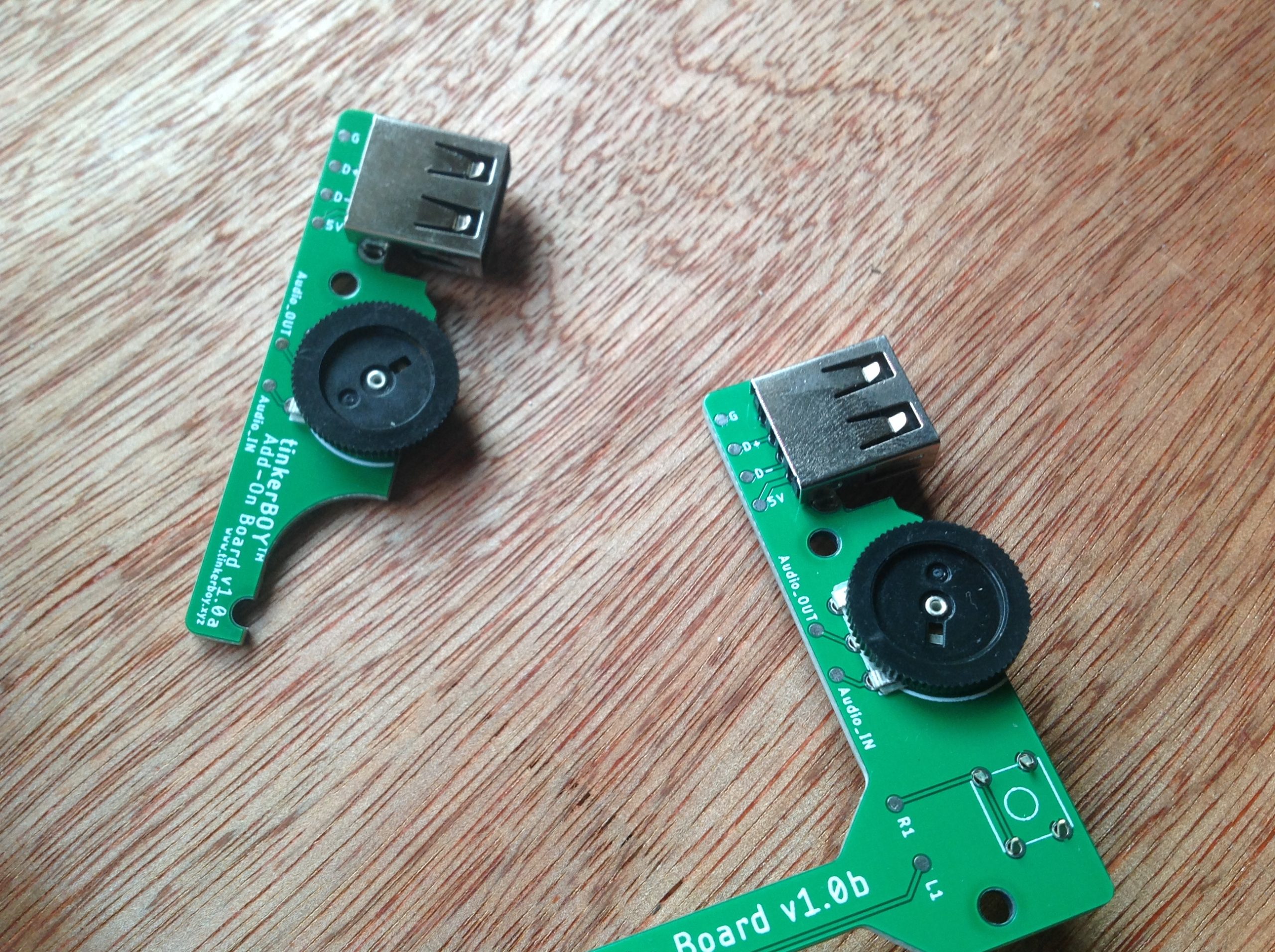
The add-on boards are for the volume wheel and usb female port. One with builtin tactile buttons and the other without it for those who prefer other back buttons.
I will be testing them and will post update.
Got my pcb orders yesterday and was very excited to assemble one. Unfortunately it didn’t work on my first test. It’s abnormally consuming too much power around 1A without even a load on it and the output voltage is way below 5v. 🙁 I went to view the schematics again and found out that I connected some of the components wrong. So I tried cutting some traces and re-routed some of the components. I re-tested it again and this time the output voltage is 5.2v and consumption without load is just what I expected. It works! 🙂
Well, not really. Haha..? I read somewhere before that it’s very important to use short and wide traces for high switching boost converter but obviously I forgot to consider that with the design of my PowerSwitch. Eugene also mentioned something about this on my Facebook page. This is probably the reason why i’m hearing a high-pitched squealing noise when powering a Pi 3. What do you think?
I’m currently working on a power board for Game Boy Zero which I will be calling the tinkerBOY PowerSwitch. It’s supposed to be a builtin upgrade for my tinkerBOY Controller v3.0 but I decided to design it separately and integrate a slide switch. This way, it’s not limited to just my v3 but can be used by anyone using any controller board as well as my other controllers like the v1.1, v1.2, v2.0.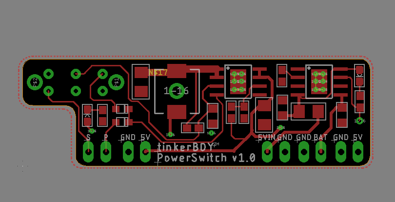
The 3 most important features will be 5V boost, battery charger, and a safe shutdown feature. I’m almost done with the design and I will be ordering some PBCs soon so I can test it. So don’t forget to subscribe to my facebook page at https://www.facebook.com/tinkerBOY/ for updates.
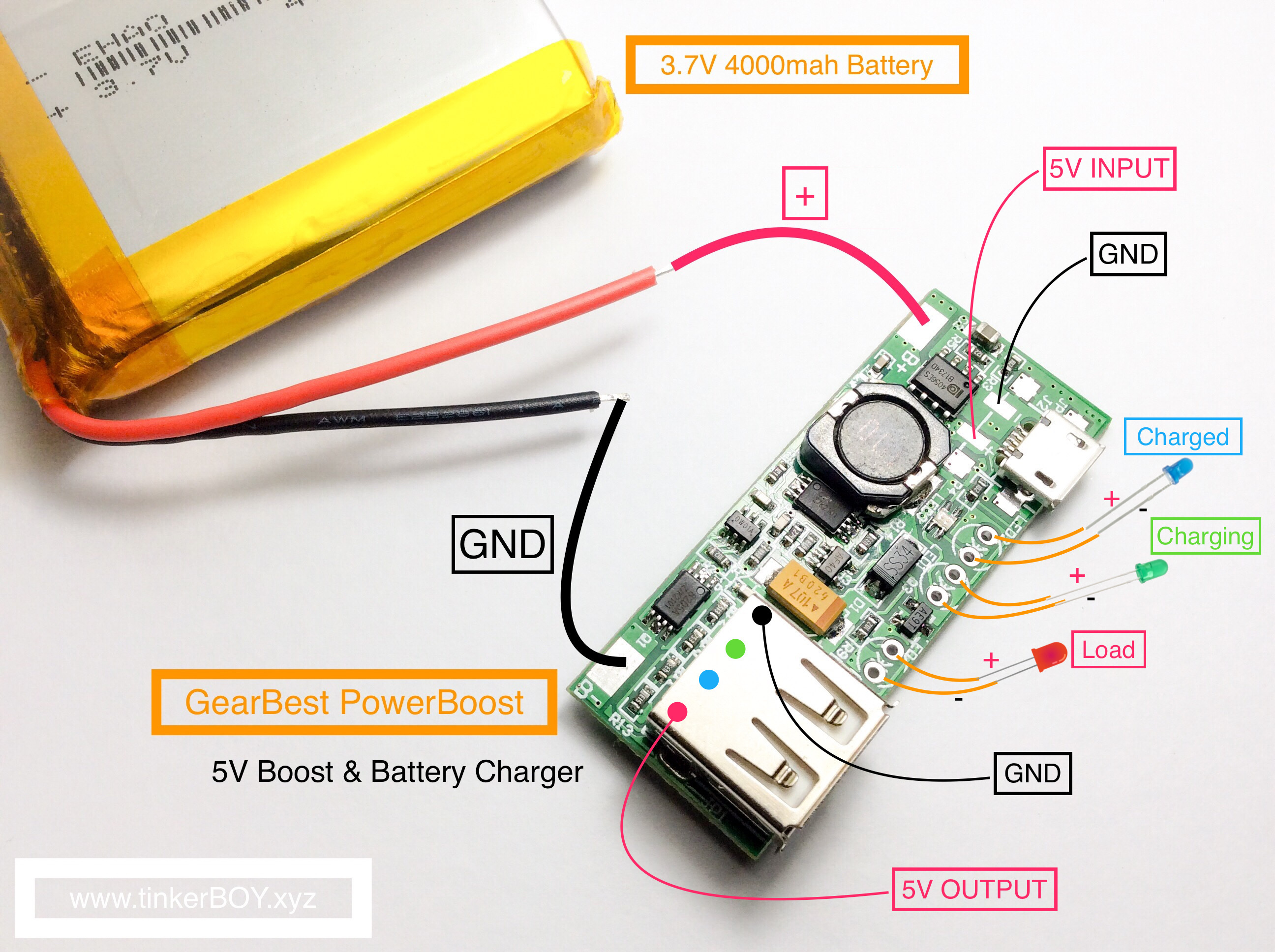
Here are pinout diagrams for the GearBest PowerBoost.
Top:
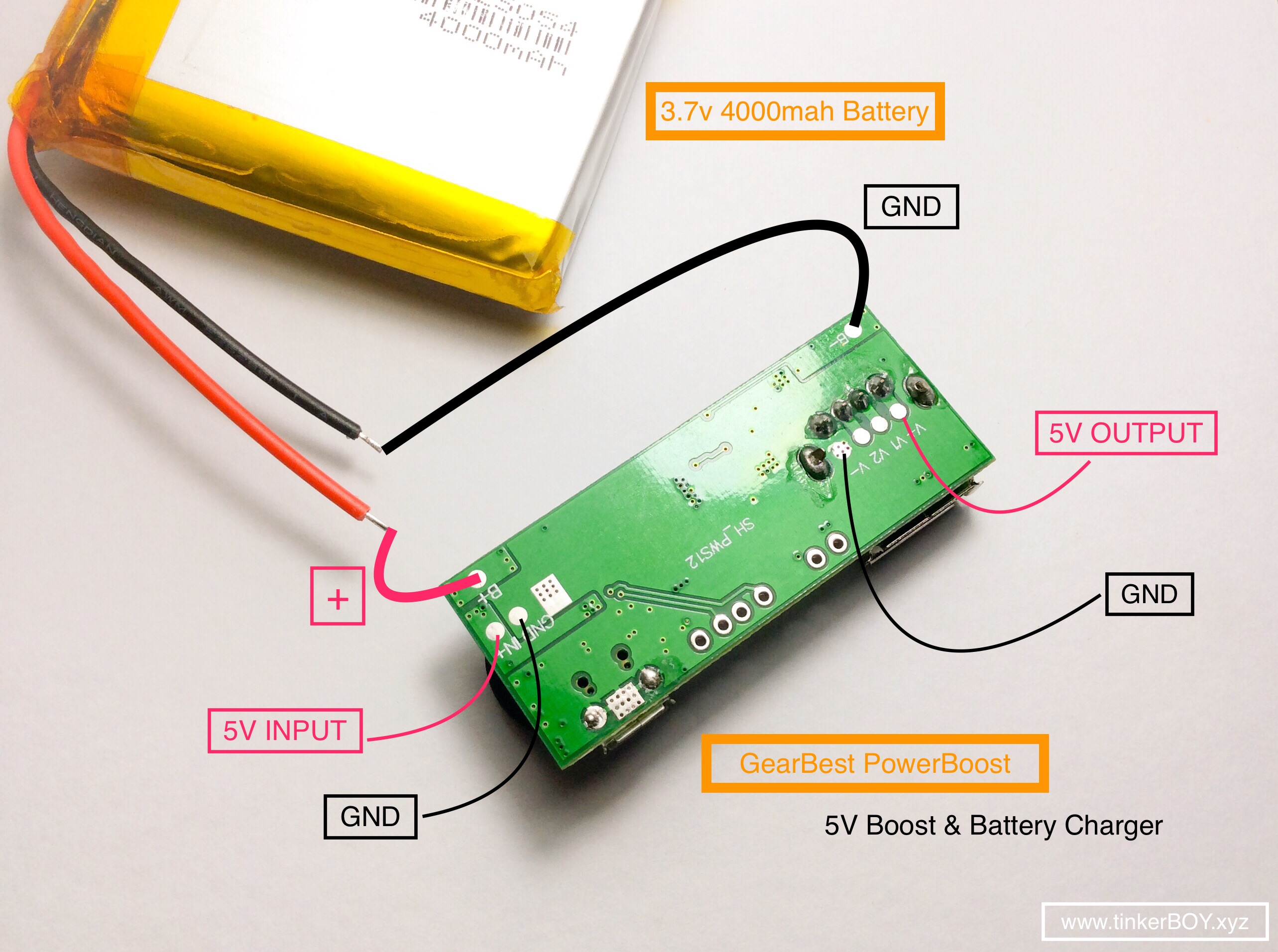
Bottom:
How to wire an SPDT slide switch:
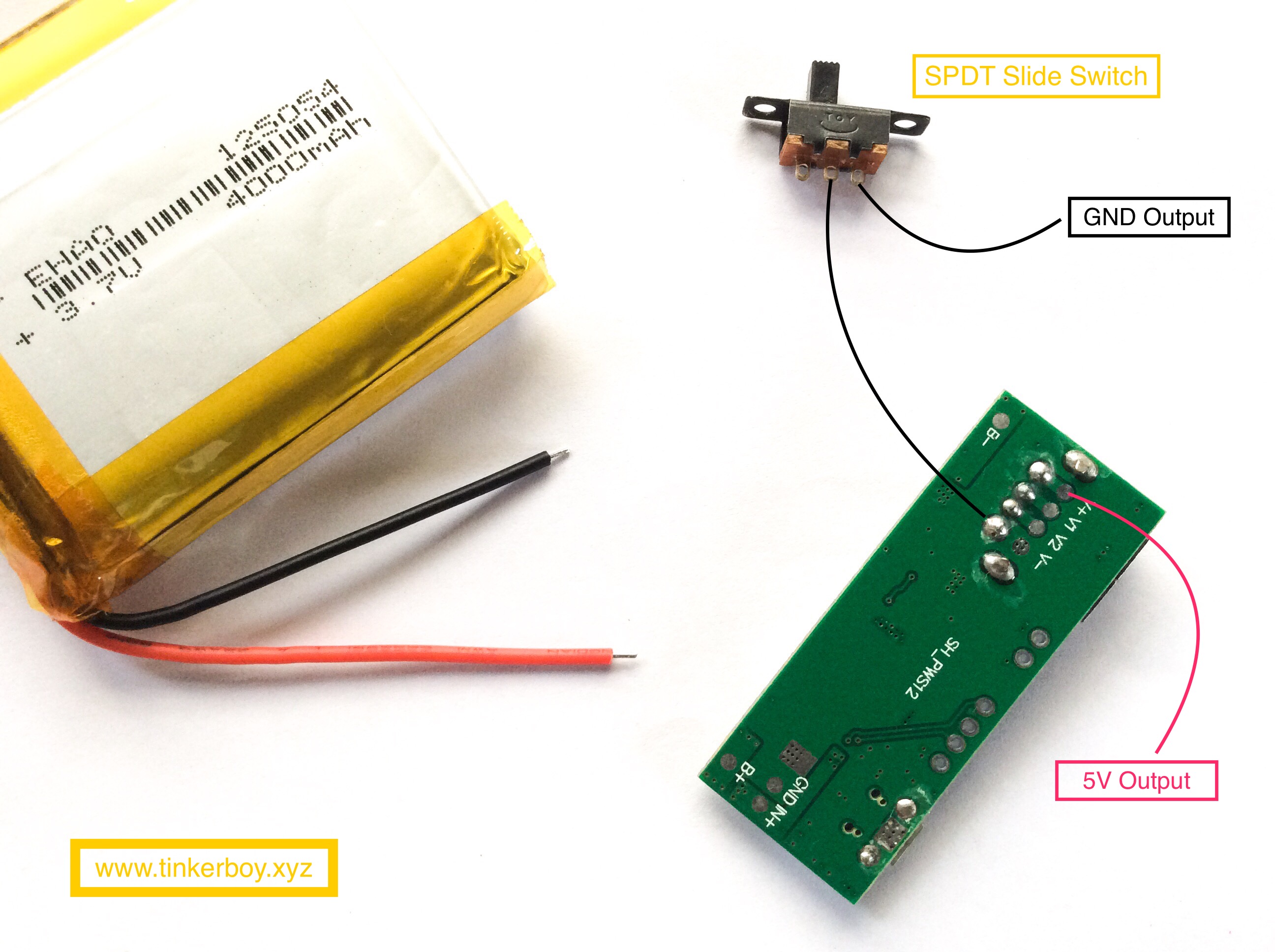
5V and GND output goes to the power input on any of my tinkerBOY Controller board.