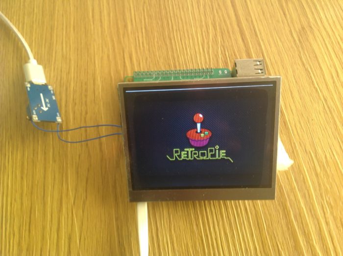
I got asked a few times about the difference of each of the 3 Game Boy Controllers I currently sell so I’ll try my best to explain it here. I’m talking about my Game Boy Controller v1.1, Game Boy Controller 2.0, and Game Boy Controller v2.1.
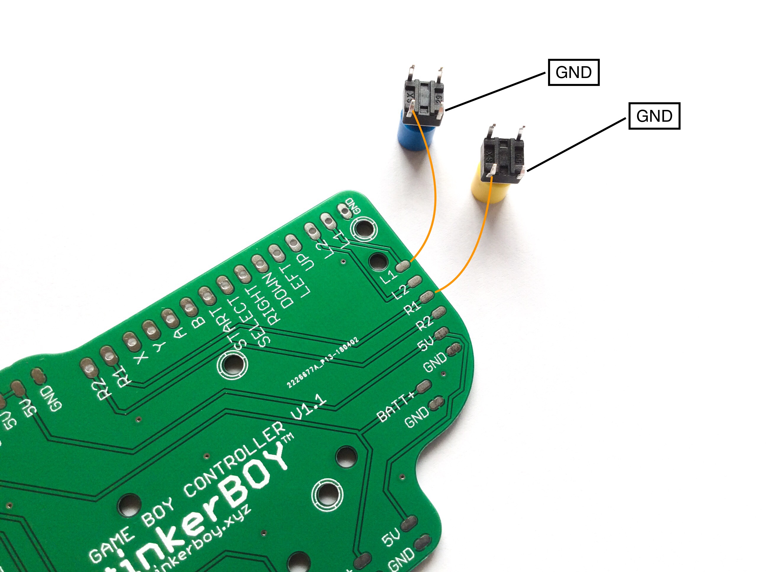
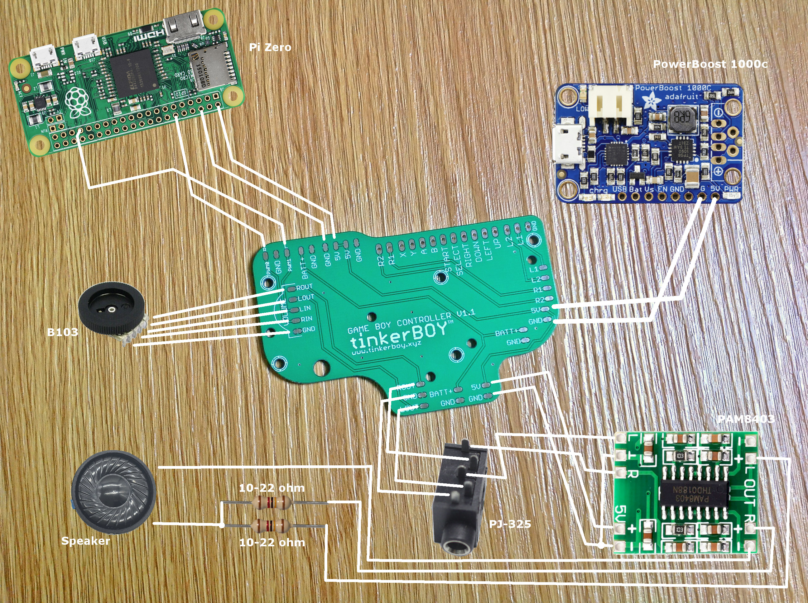
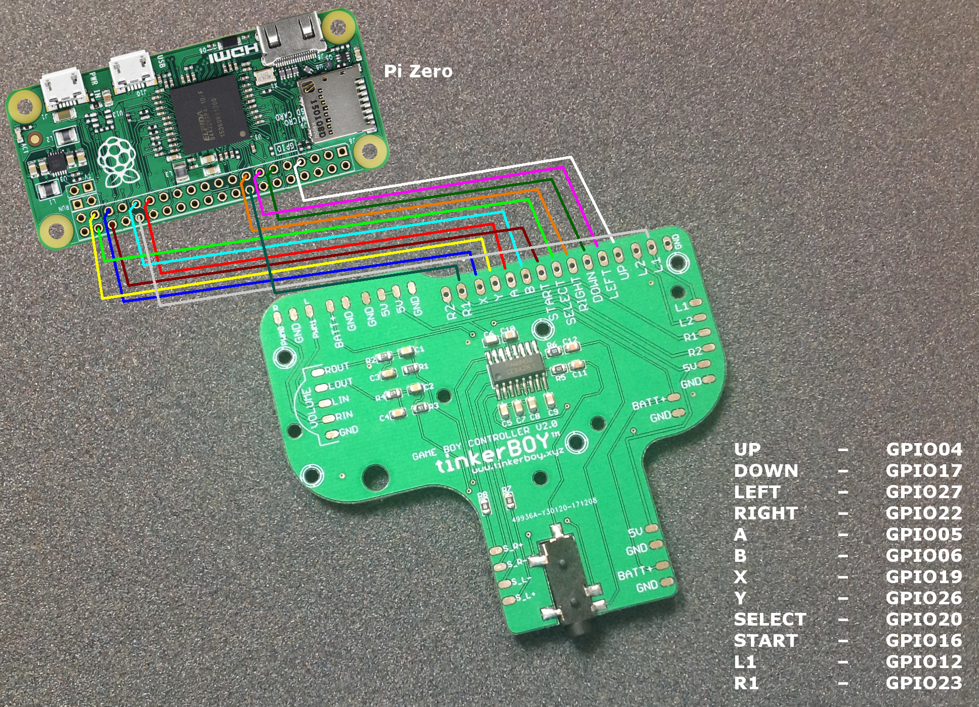
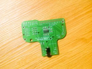
Game Boy Controller v1.1
This is one of the first boards I designed while learning Eagle software and electronics. Most of the boards that were available when I started building Game Boy Zero were not really solder-friendly and were just plain sim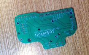 ple PCB with only solder pads for the controller buttons. So I designed one in order to make it easier to solder and included some useful features like builtin power strips, audio and volume wheel solder pads which is inspired by Helder‘s work. I think got the idea of building one from rolf.
So what does it do? Just like any simple Game Boy Common Ground PCB it just does one thing and that is to provide controller/button inputs for the Game Boy Zero only. Although I made my v1.1 a little easier on the soldering side and added some useful features I mentioned above. But of course you need more than a simple pcb to build a proper working Game Boy Zero. Aside from the Game Boy case, screen, battery, Pi Zero, 5v boost and charger module, you also need an audio amp, speaker, a low/high pass filter, headphone jack, etc..
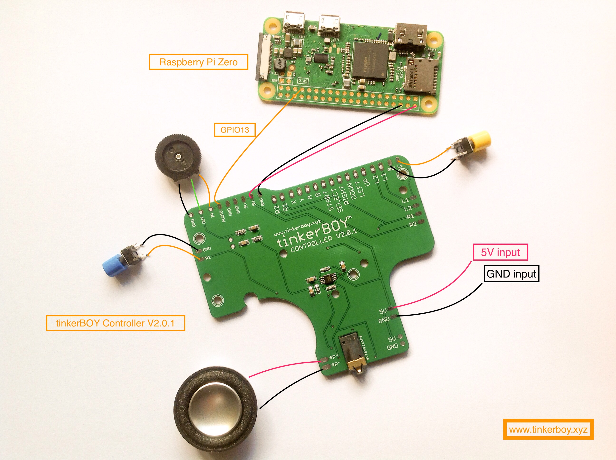
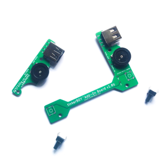
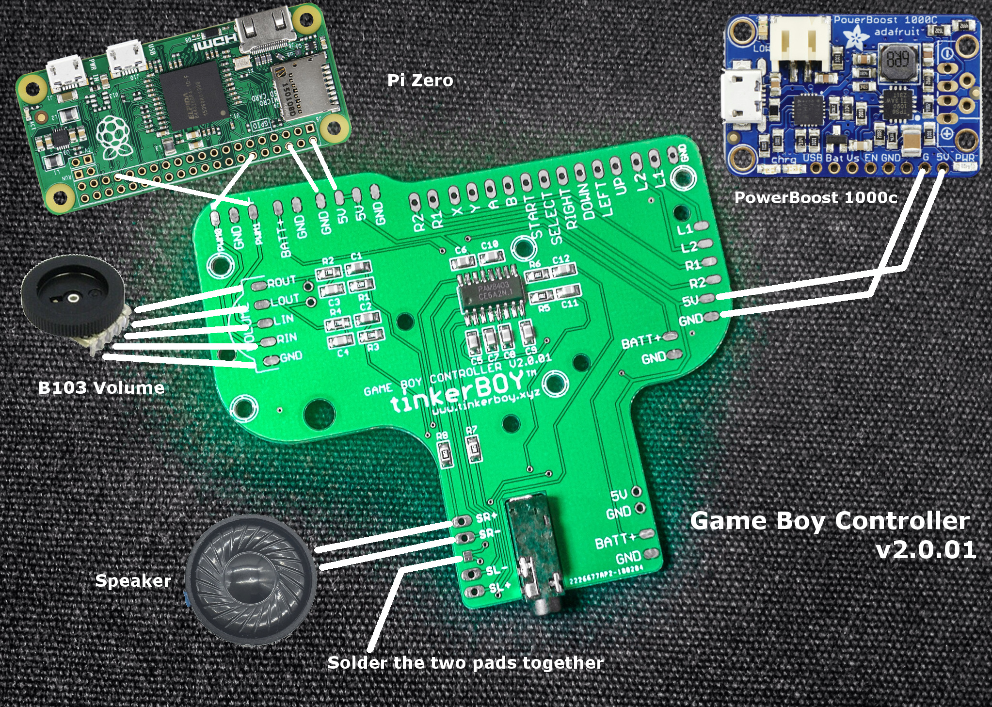
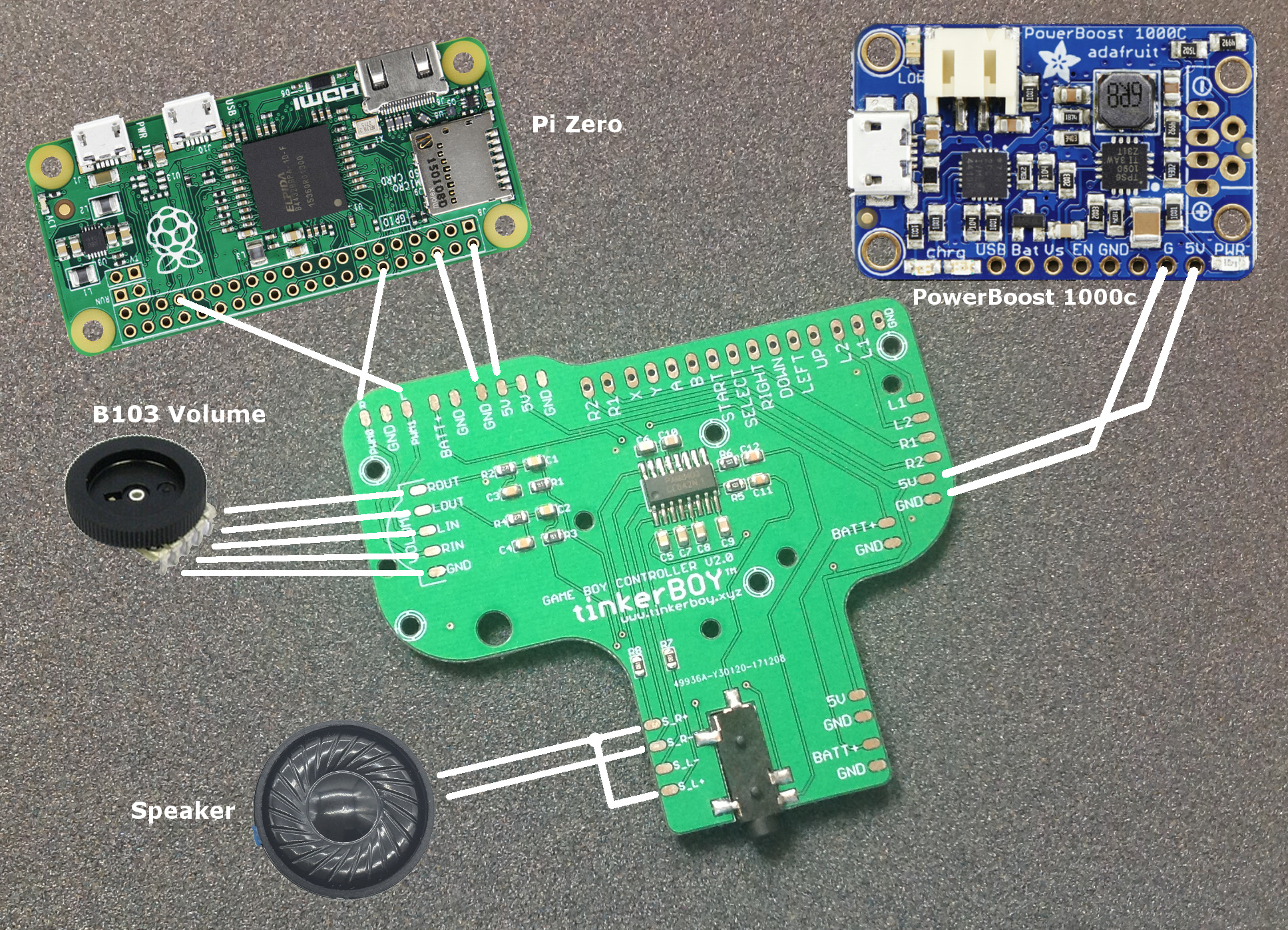
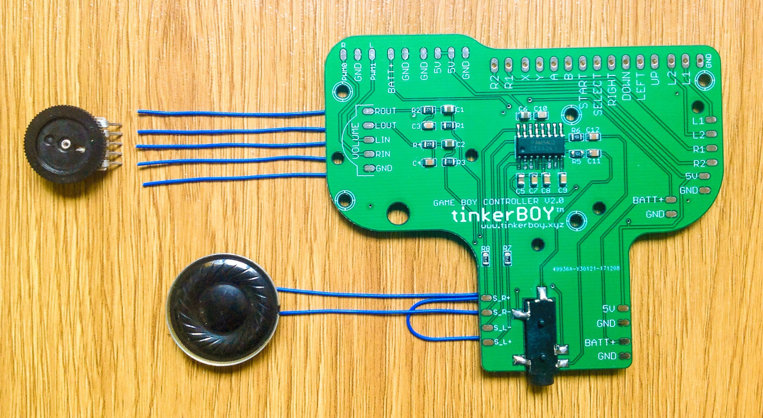
Game Boy Controller v2.0
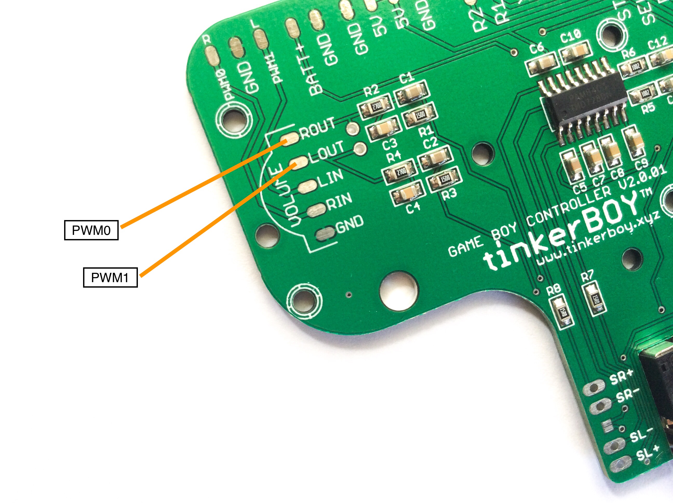
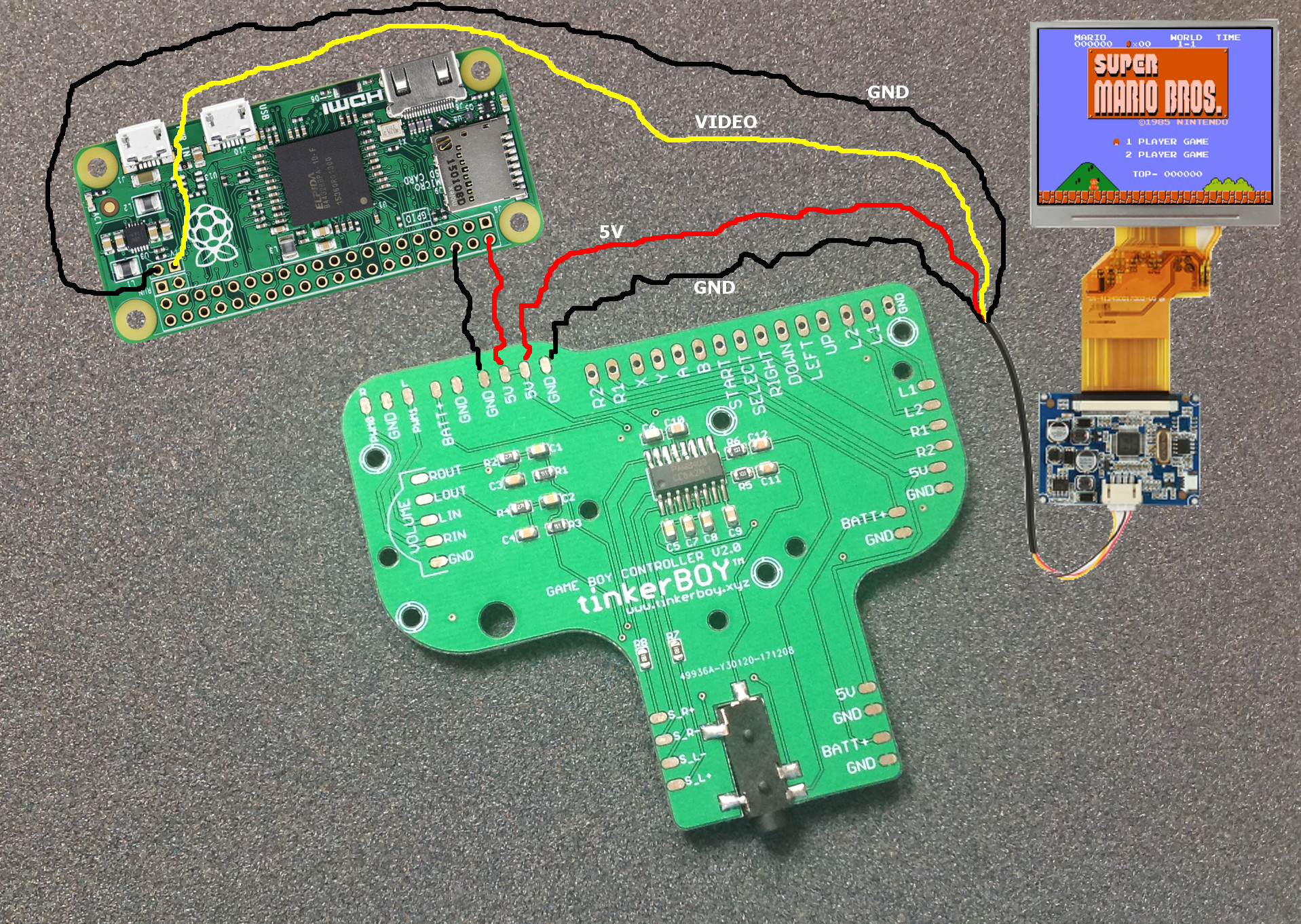
I have built and sold a lot of GBZs and GB3s here in the Philippines using just a simple PCB button which requires a lot of work and soldering because there wasn’t much available option. So I decided to make my own. Here comes my Game Boy Controller v2.0 which includes the low/high pass filter, PAM8403 audio amp, and a headphone jack already builtin to it. It’s similar to Helder’s Audio Board which I got the inspiration from and since the schematics for the PAM8403 and the low/pass filter are easily obtainable.
So what’s the advantage over the v1.1? It may seem simple to build, but soldering and wiring a separate audio amp, low/high pass filter, headpone jack, and the volume wheel is pretty confusing to most and requires some basic electronics and troubleshooting skill. The v2.0 should save you time from figuring out and soldering the audio part of a Game Boy Zero build.
Another important advantage is it’s simplicity. It does not use any USB device for the audio and controllers so you get to keep the only USB port on a Pi Zero for external use. This is not an issue with a Pi 3 build since it has plenty of USB ports. Which lead me to my next board.
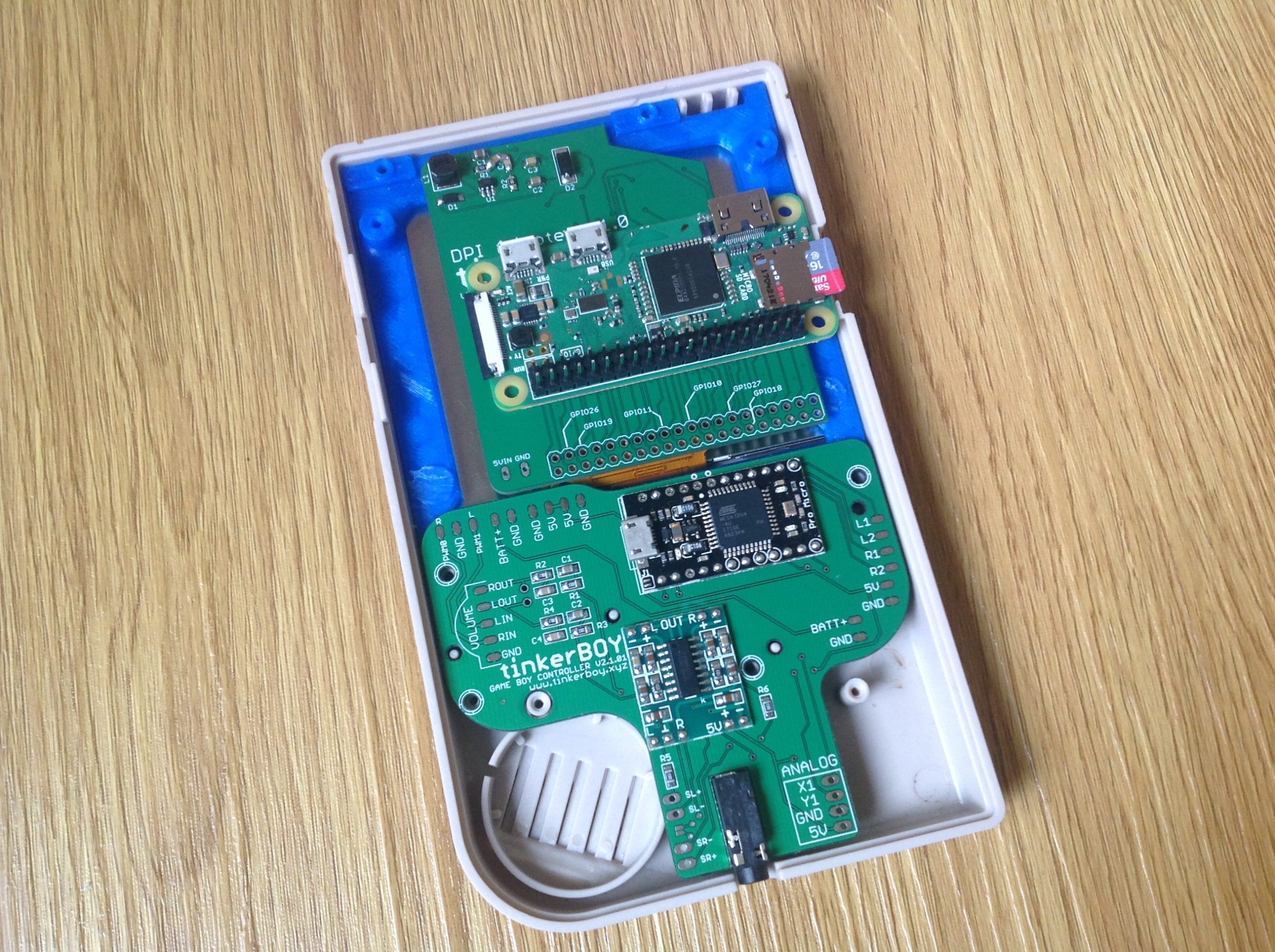
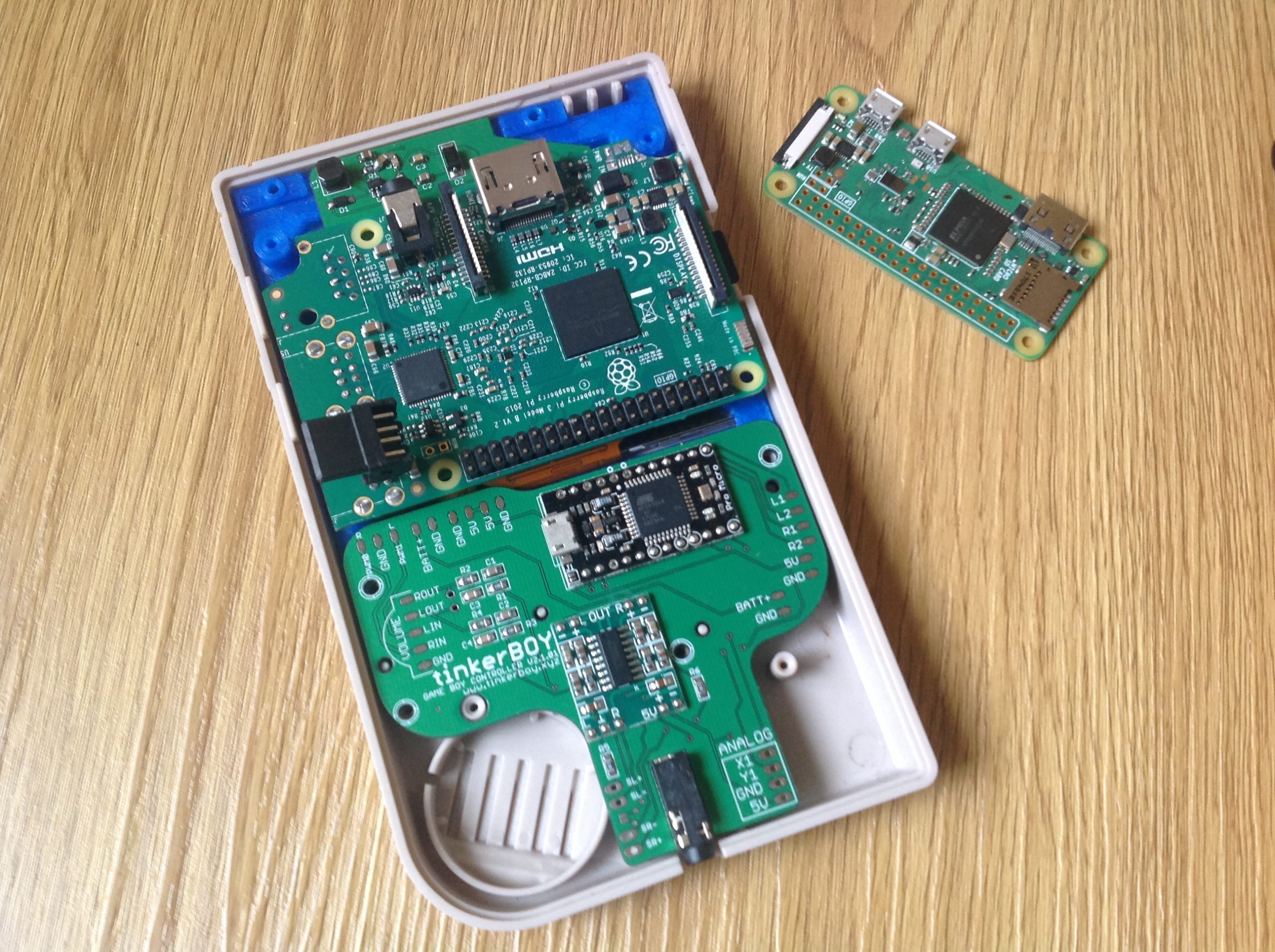
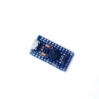
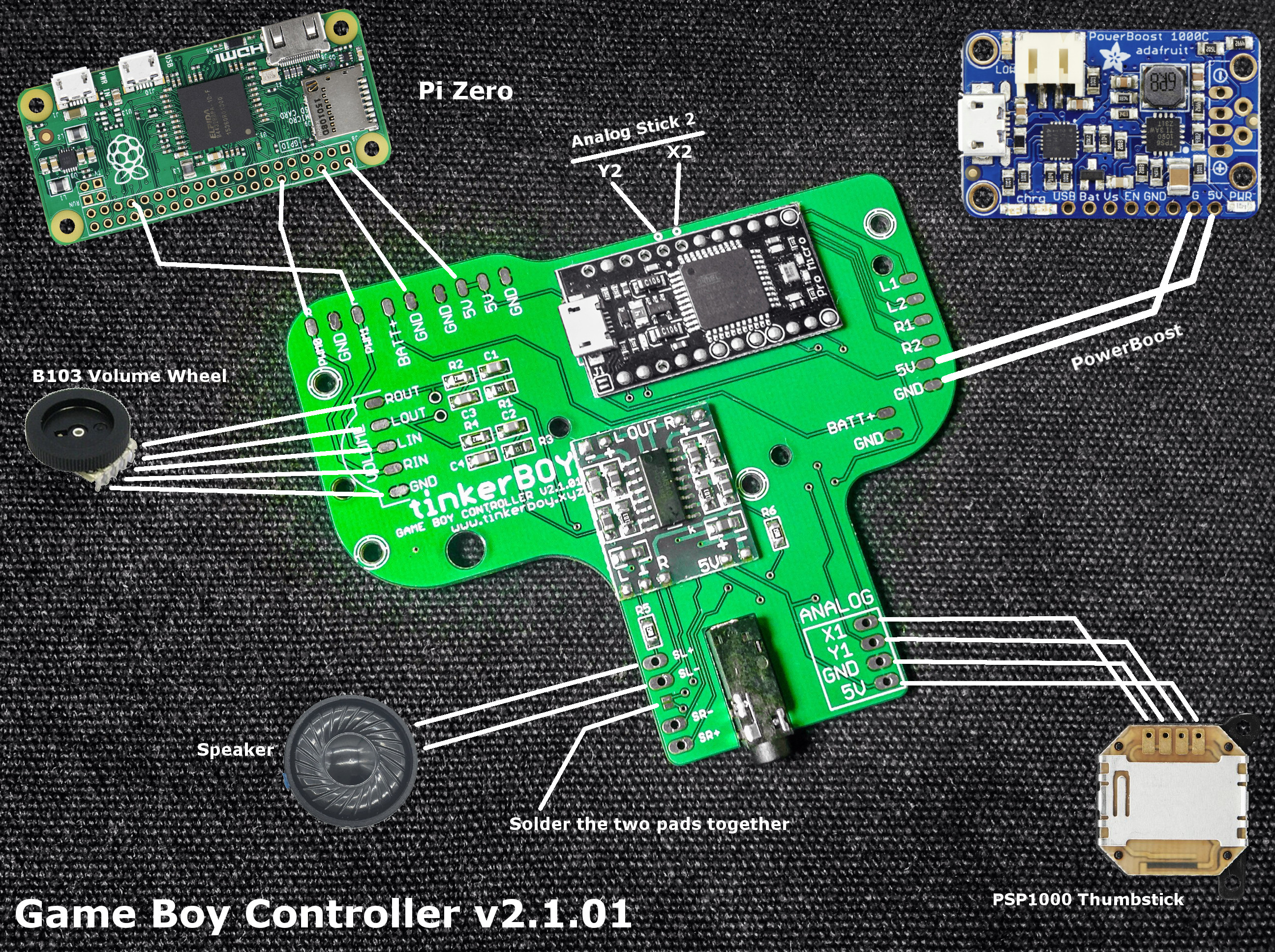
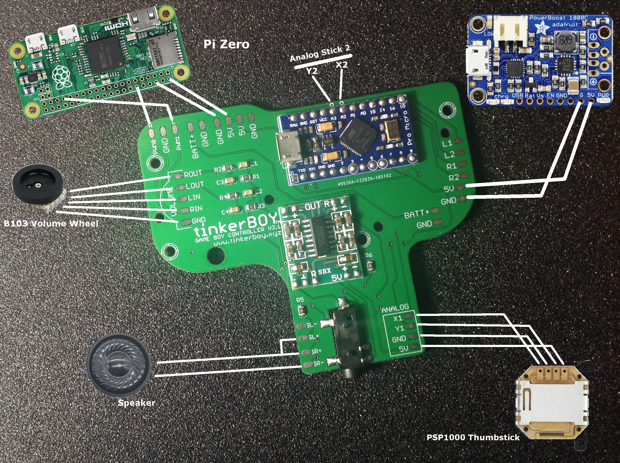
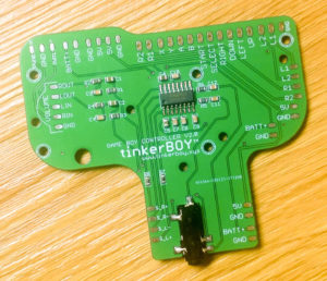
Game Boy Controller v2.1

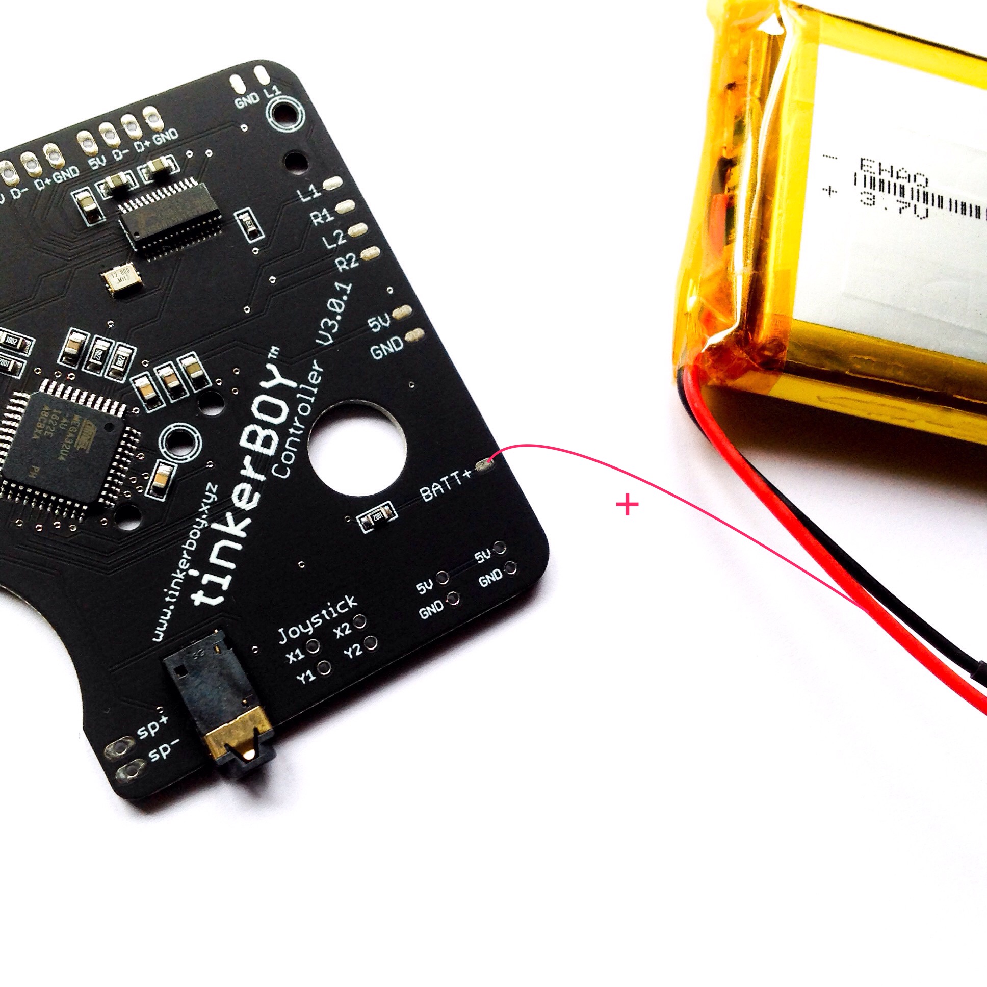
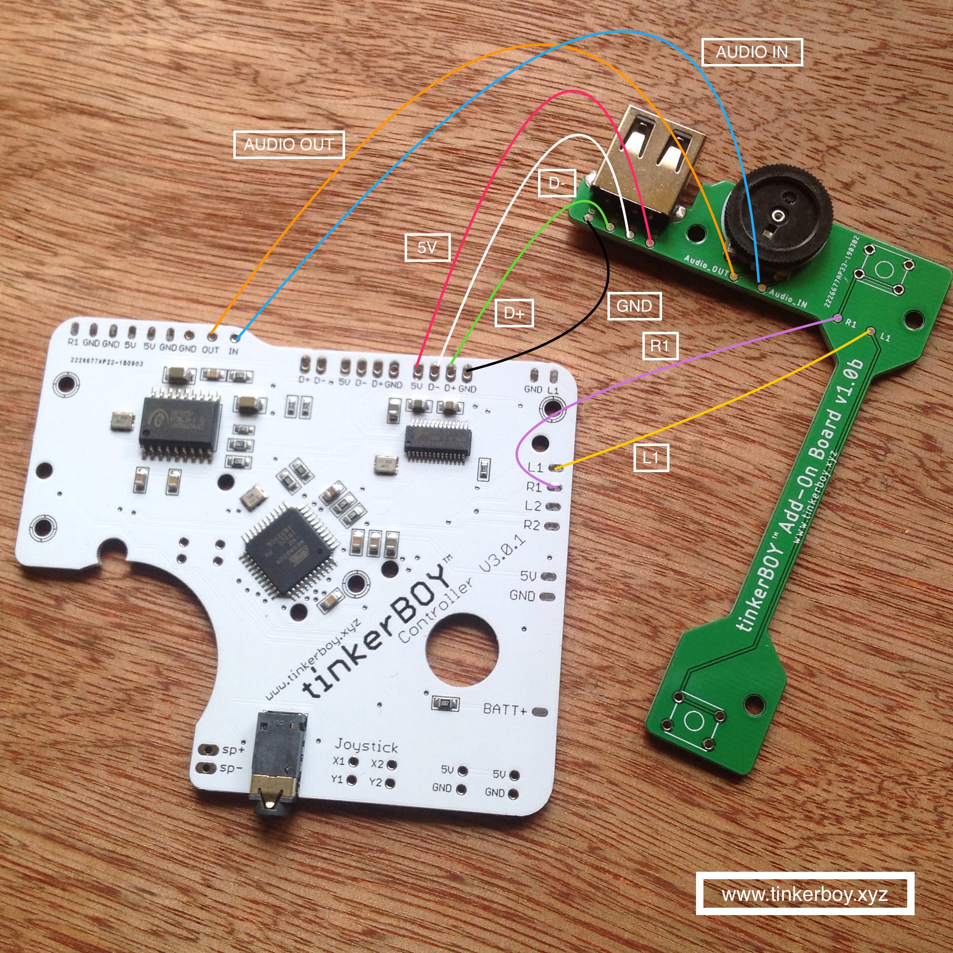
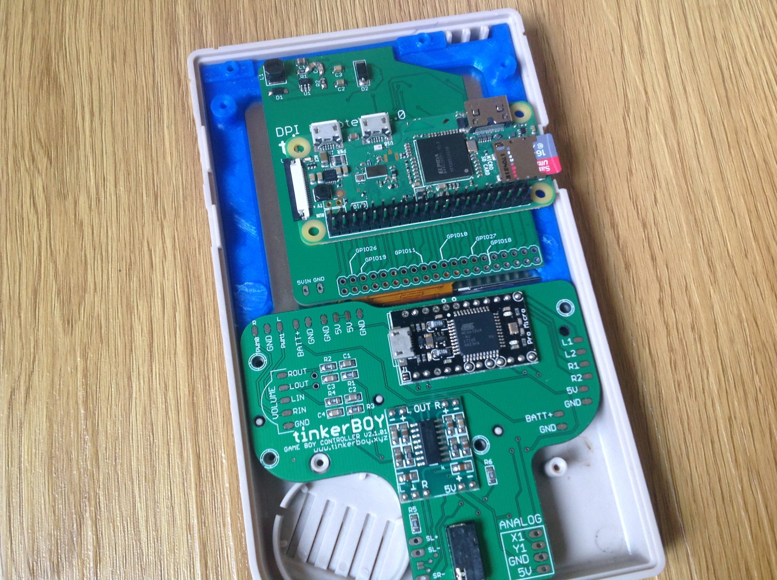
My Game Boy Controller v2.1 has all the builtin features of my v2.0 board but instead of using the Pi’s GPIO pins, it uses a USB-based Arduino Pro Micro module for the controllers which practically reduces the number of wires to solder. You only need to solder 2 connection wires while my v2.0 and v1.1 board need atleast 10 button connections excluding the L and Rs.
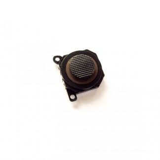
Another advantage is the Analog Stick support which you cannot do on a v1.1 or v2.0 board without buying a separate Pro Micro or a Teensy module. While it’s perfect for Pi3 builds, it takes away the only usb port on a Pi Zero unless you consider an external usb hub for it. Which again lead me to my next board.
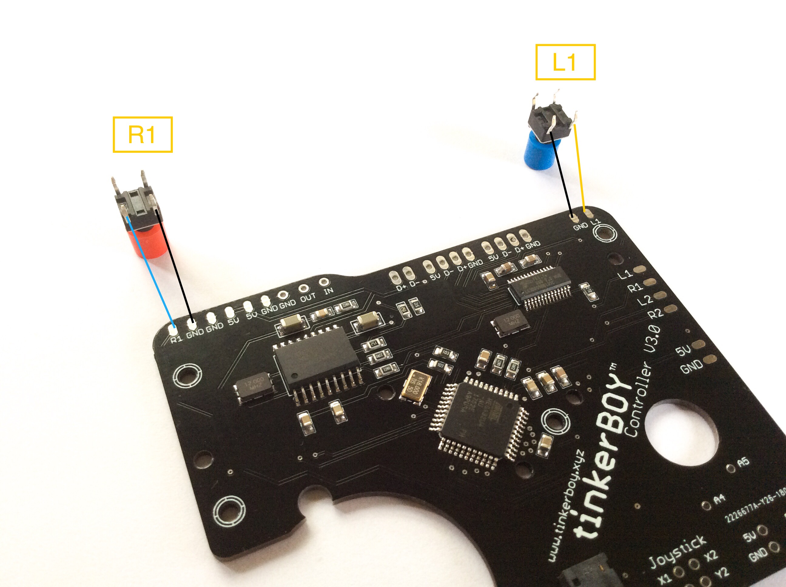
Game Boy Controller v3.0
I’m still working on this one. 🙂 Features should include a builtin USB audio, amp, atmega32u4, etc.
So, that’s it for now. I hope you found this information helpful in building your own Game Boy Zero. Please don’t hesitate to contact me for any help or advice.