Posted on 8 Comments

DPI Adapter + Game Boy Controller = AIO

Update: tinkerBOY DPI Adapter v1.0 now available!

I finally had time to populate and test my DPI adapter prototype which will be included as part of my all-in-one board for Game Boy Zero / 3. So far it’s working fine. The DPI screen looks way better than composite.

I actually built a Game Boy 3 using just a simple FPC breakout board for doing the DPI connections but it was very difficult to make it work. Obviously because of all the wires I soldered to the Pi which are prone to interference. But I managed to make it work anyway. So I made a prototype to make it easier to use a DPI screen.

The AIO board will be compatible with Raspberry Pi Zero and Pi 3. Both will have sdcard access from the “CONTRAST” area of the Game Boy case.

Posted on Leave a comment

RetroPie: Testing The USB Controller/Joystick Via The Command Line or Terminal

Let’s start by connecting to your Raspberry Pi/RetroPie either by SSH or just plug a keyboard and hit F4 to go directly to the Terminal.

Check if your USB controller is detected by:

lsusb

Mine is “Arduino SA Leonardo”.

Next, enter the following command to test the inputs:

jstest /dev/input/js0

Now press each of the configured button inputs and you should get a response.

Posted on 10 Comments

Wiring Guide for Game Boy Controller v1.1

The pwm audio on the Pi Zero is horrible and noisy so you probably be needing a low/high pass filter too.

For the controllers, you can visit GPIO Button Guide for Game Boy Controller v2.0 / v2.1.

Additional Parts You May Need:

Posted on 17 Comments

GPIO Button Guide for Game Boy Controller v2.0 / v1.1

Wiring the Game Boy Controller v2.0 to the Pi Zero or Pi 3’s GPIO pins is the simplest way to configure controller inputs for the Game Boy Zero/3 without any additional component. You can use the following diagram to solder the button inputs to the Pi and download a copy of RetroPie with the GPIO program already pre-installed.

Posted on 3 Comments

Game Boy Controller V2.0 Audio Wiring Guide

Stereo Audio with Single Speaker Setup

This setup uses both left and audio channel.

  1. Solder a wire from the PWM0-R pad to the Pi Zero’s GPIO18 pin or the Pi 3’s right audio from the headphone jack.
  2. Solder a wire from the PWM1-L pad to the Pi Zero’s GPIO13 pin or the Pi 3’s left audio from the headphone jack.
  3. Solder the volume pot to the board with their respective pins. You can use a 5-pin or a 3-pin volume wheel.
  4. Solder a wire from the S_R+ pad to the speaker’s positive(+) pin.
  5. Solder a wire from the S_R- pad to the speaker’s negative(-) pin.
  6. Last step is to combine both left and audio for the speaker by soldering a jumper wire from S_R+ pad to S_L+ pad.
  7. For Pi Zero build, edit the /boot/config.txt and add the following line:
    dtoverlay=pwm-2chan,pin=18,func=2,pin2=13,func2=4

You can also use 2 speakers for left and audio output if that’s what you want.

There are different ways to setup the audio on a Game Boy Zero/3 but this is the most common and easiest way to do so good luck and happy building!

Posted on 3 Comments

Testing out my DPI Adapter for Raspberry Pi Zero and 3

Update: tinkerBOY DPI Adapter v1.0 now available!

I just got my DPI Adapter a few days ago and have been testing it earlier. I made this one to make it easier to use a DPI screen for Game Boy Zero and Game Boy 3 projects. It works on both the Pi Zero and Pi 3. There’s a builtin backlight driver but im still waiting for parts to finish it

This one is designed specifically for a commonly used 3.5″ lcd for GBZ/3.

Posted on 1 Comment

Pinout Diagrams for the PCM2704 and 3D Sound(COB) USB Sound Card Adapters

These are for the two most popular usb sound adapters with the (1) PCM2704 chip and (2) COB (chip-on-board) chip.

(1) USB Sound Card Adapter with PCM2704 chip

Top:

Bottom:

(2) 3D SOUND USB Sound Card Adapter with the COB chip

Top:

Bottom:

How to configure a USB sound card with RetroPie.


You can support me by buying the usb sound card adapter using this link  or you can donate any amount via PayPal.


Posted on 4 Comments

RetroPie/Raspberry Pi: How to Configure a USB Sound Device

Step 1

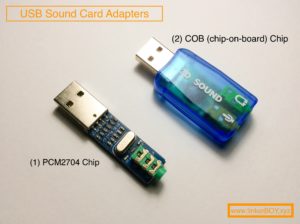
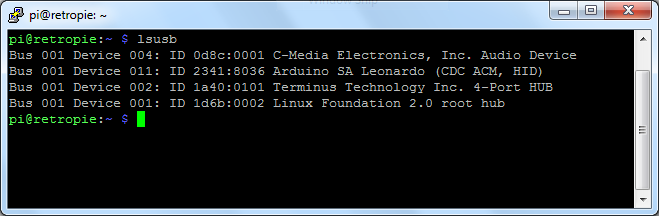
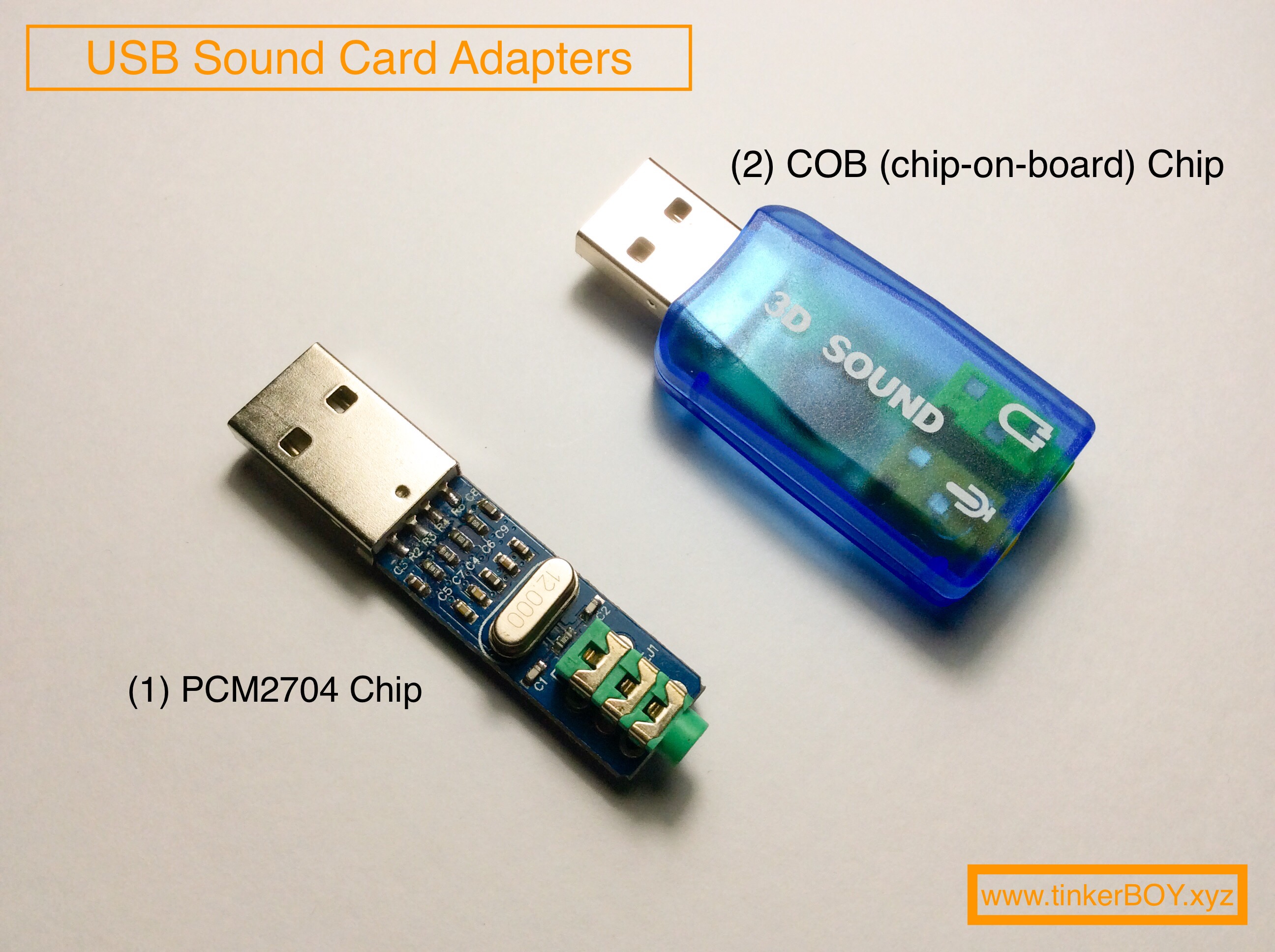
Plug in your usb sound adapter/device into the Raspberry Pi’s usb port and let’s make sure it’s detected. Enter the following command.

pi@retropie:~ $ lsusb

You should get something like

Bus 001 Device 005: ID 0079:0011 DragonRise Inc. Gamepad
Bus 001 Device 004: ID 7392:7711 Edimax Technology Co., Ltd EW-7711UTn nLite Wireless Adapter [Ralink RT2870]
Bus 001 Device 003: ID 08bb:2704 Texas Instruments Audio Codec
Bus 001 Device 002: ID 1a40:0101 Terminus Technology Inc. 4-Port HUB
Bus 001 Device 001: ID 1d6b:0002 Linux Foundation 2.0 root hub
pi@retropie:~ $

Mine is detected as “Bus 001 Device 003: ID 08bb:2704 Texas Instruments Audio Codec“.

Step 2

Type and enter the following command to check the list of sound device being used by the system and take note of the order number.

pi@retropie:~ $ cat /proc/asound/modules

You should get something like

0 snd_bcm2835
1 snd_usb_audio
pi@retropie:~ $

My usb sound adapter is on order number 1.

Step 3

Let’s change the default sound to “1 snd_usb_audio” by editing

pi@retropie:~ $ sudo nano /etc/asound.conf

Paste the following

pcm.!default {
type hw
card 1
}
ctl.!default {
type hw
card 1
}

Reboot and it should use the usb sound as the default.

Sound Test

Enter the following command to test the left and right audio channel:

speaker-test -c2 -twav -l7

You should hear a sound coming from the left and right channel.

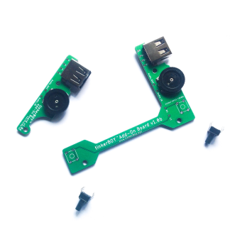
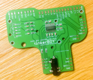
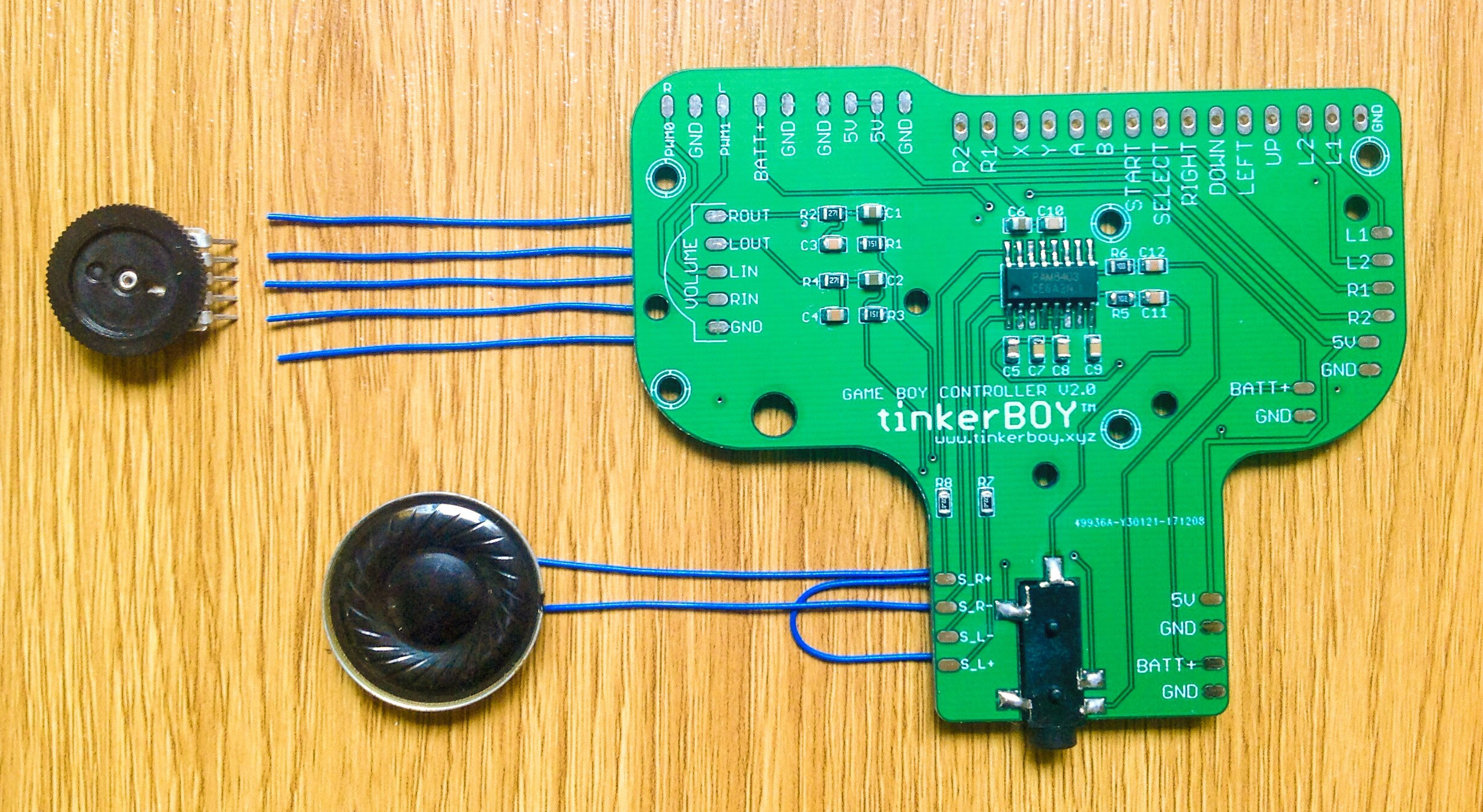
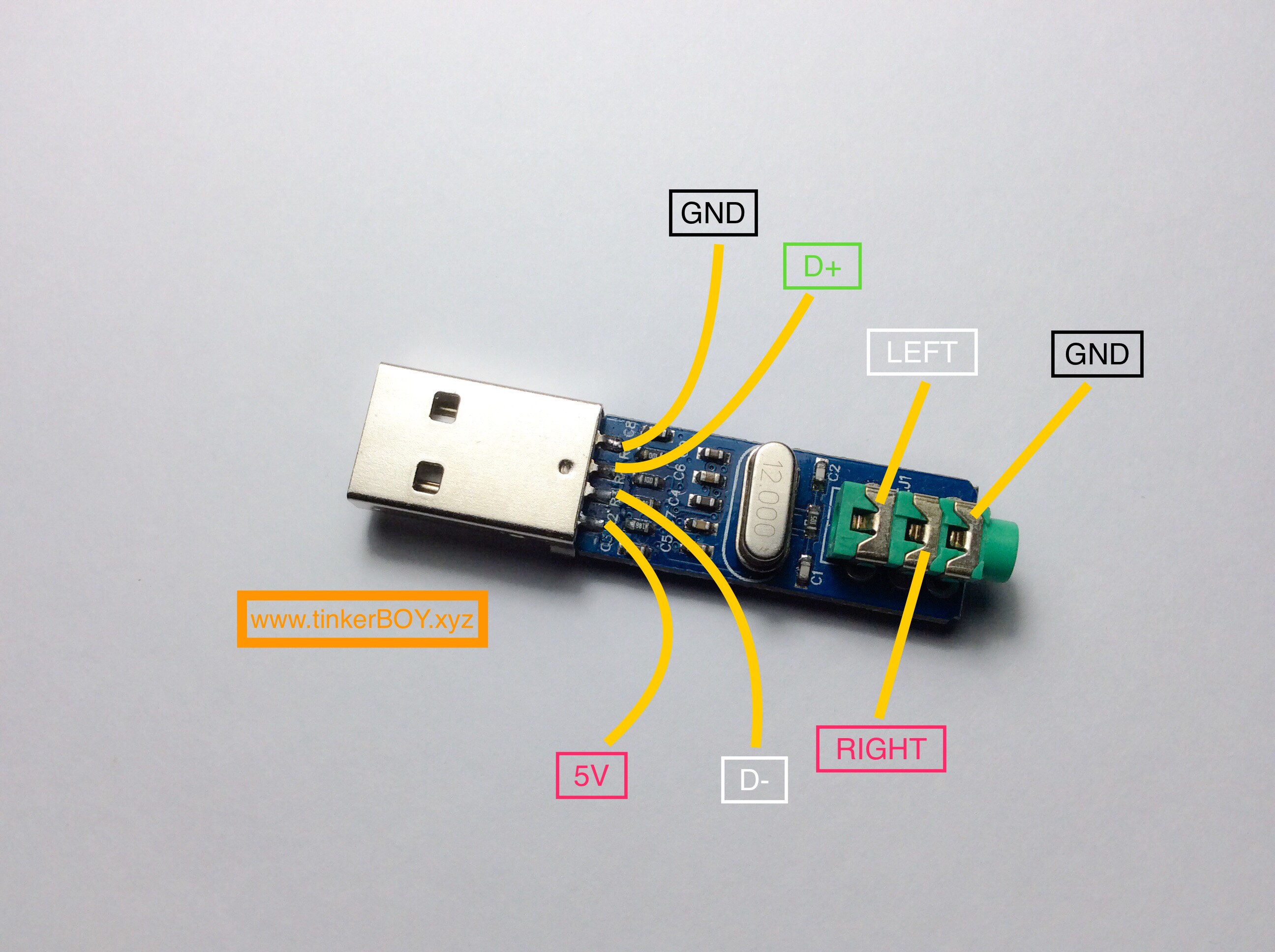
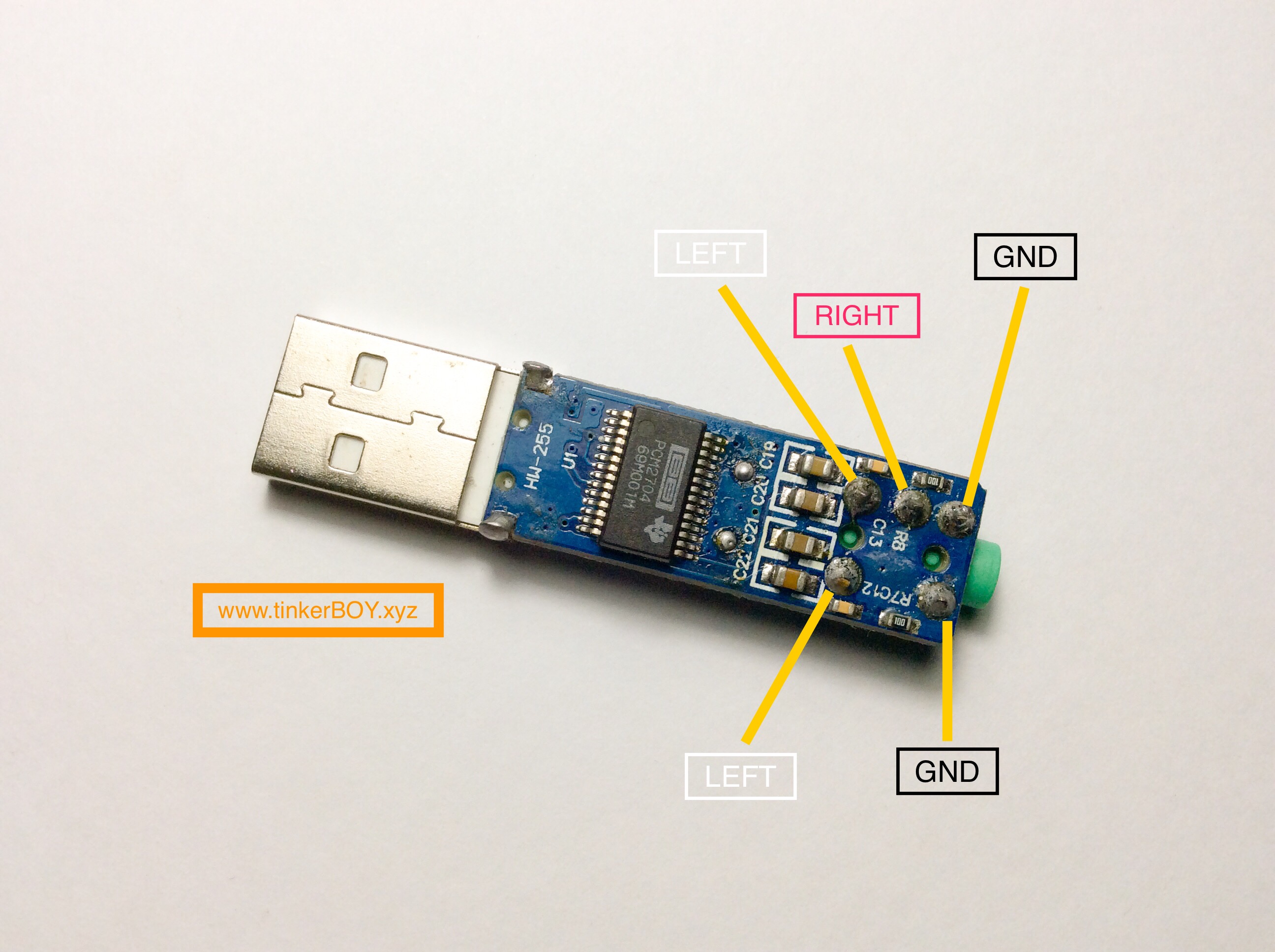
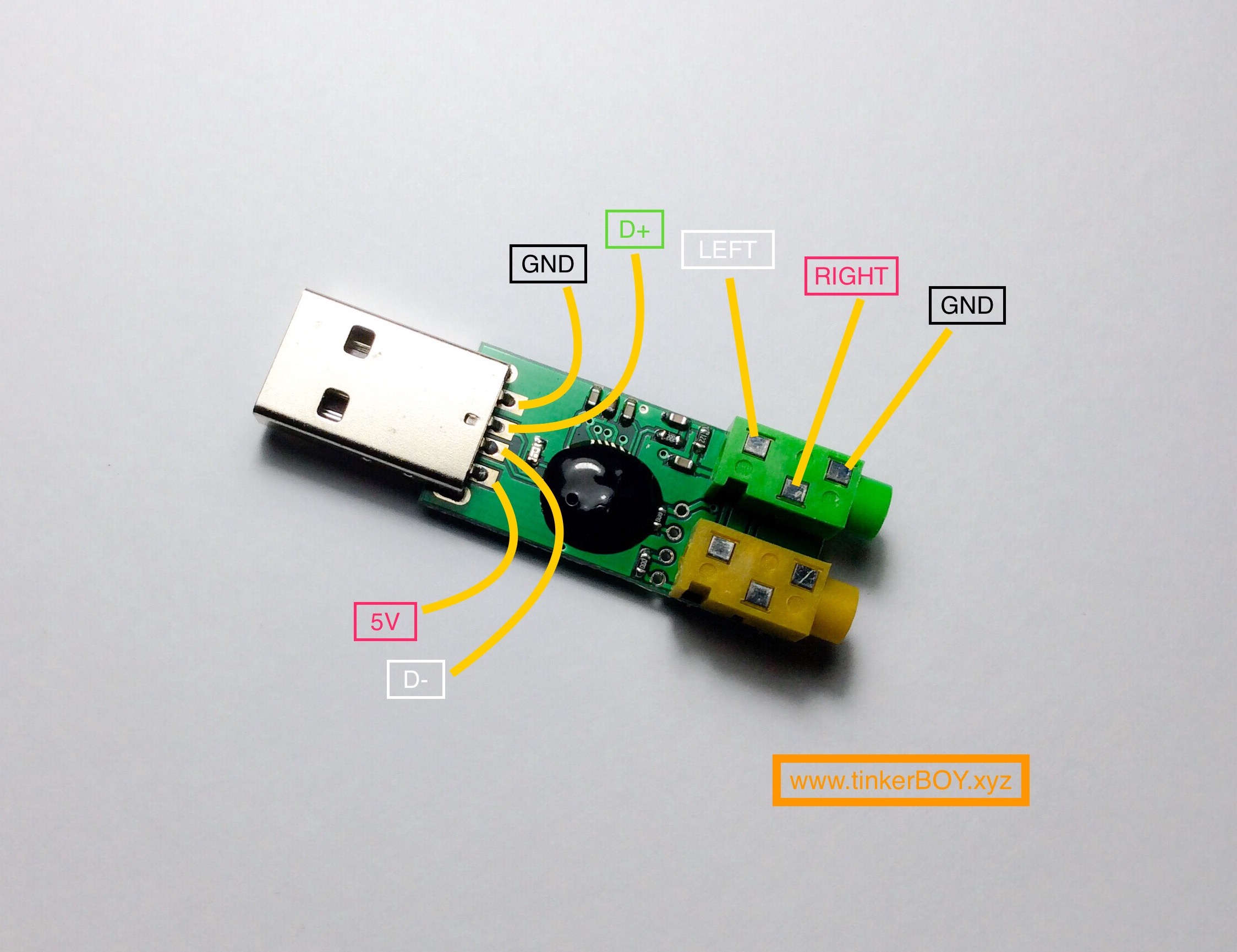
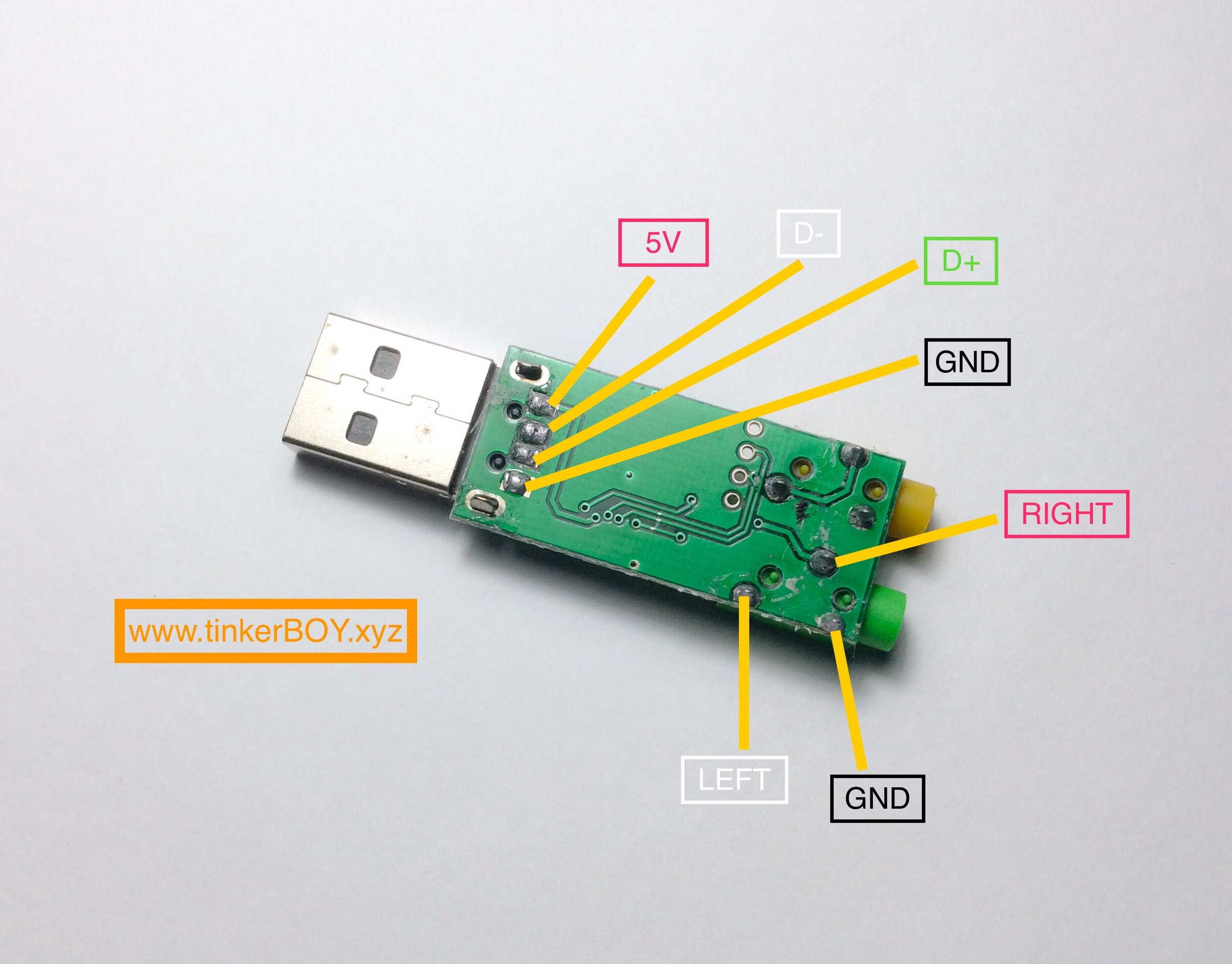
=> Pinout Diagrams for the PCM2704 and 3D Sound(COB) USB Sound Card Adapters.

You can also use another method at RetroPie: Configure USB Audio As Primary Sound Device.
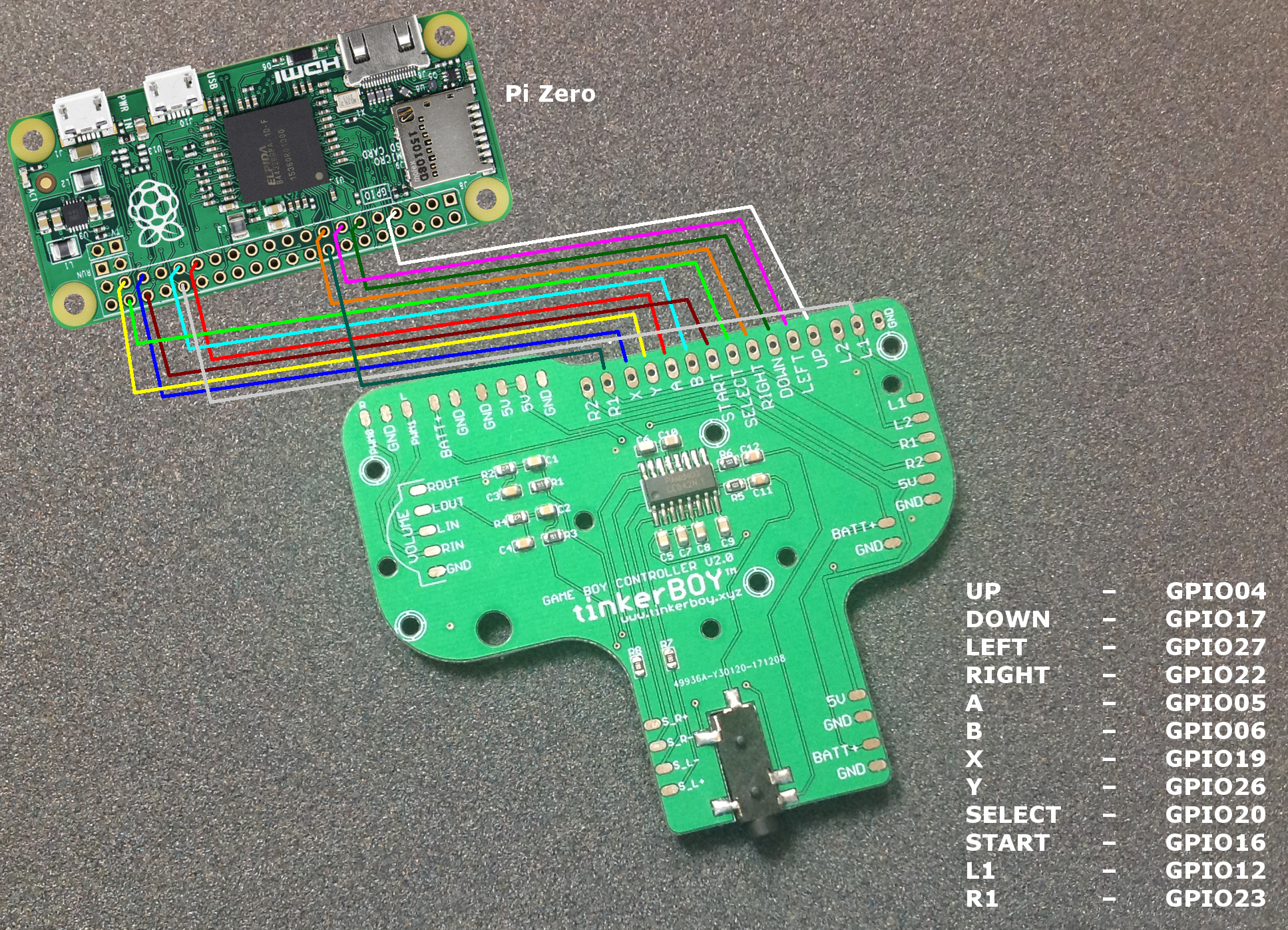
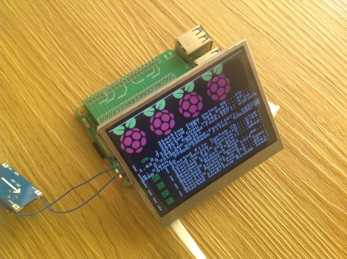
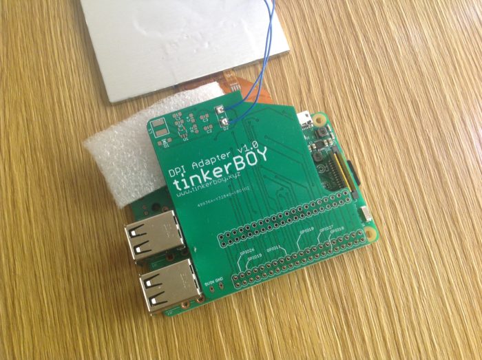