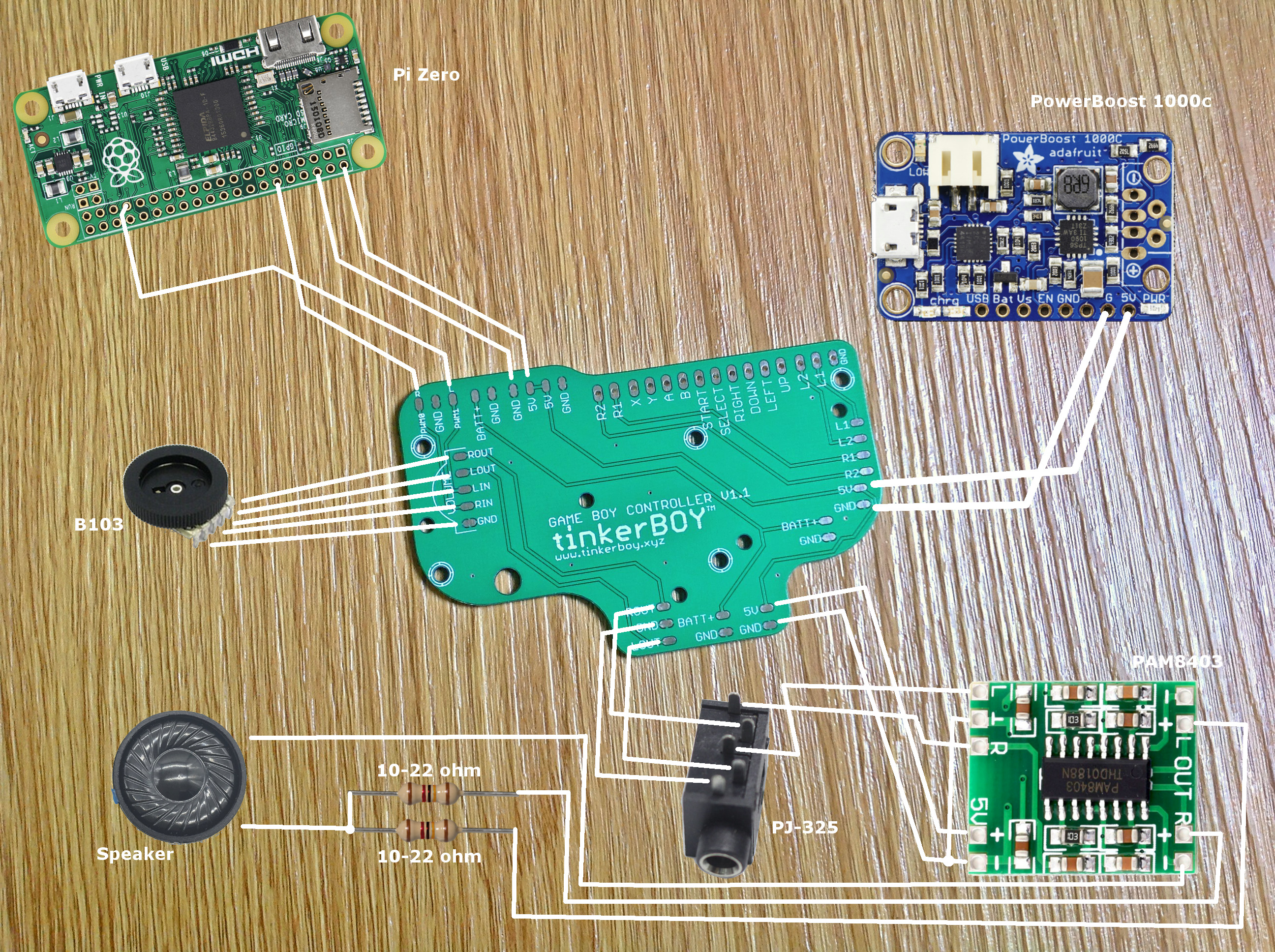
The pwm audio on the Pi Zero is horrible and noisy so you probably be needing a low/high pass filter too.
For the controllers, you can visit GPIO Button Guide for Game Boy Controller v2.0 / v2.1.
Additional Parts You May Need:
-
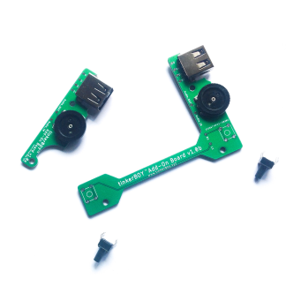
tinkerBOY Add-On Board – with Pre-soldered USB Type A Port and 3-Pin Volume Wheel, Back Buttons
Select options This product has multiple variants. The options may be chosen on the product page -
tinkerBOY Speaker 4Ω2W / 8Ω1W
Select options This product has multiple variants. The options may be chosen on the product page -
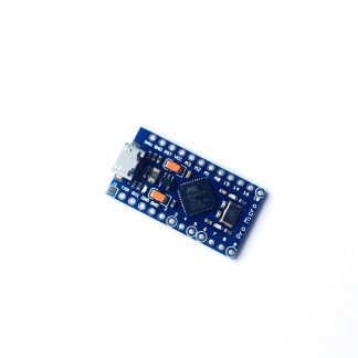
Arduino Pro Micro Compatible with Atmega32u4
Add to cart -
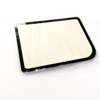
Game Boy Zero Glass Screen Cover Protector
Select options This product has multiple variants. The options may be chosen on the product page -
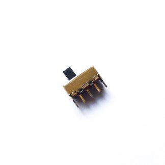
SPDT Slide Switch 1P2T for Game Boy Zero
Add to cart -
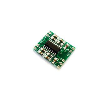
PAM8403 Dual Channel 3W+3W Stereo Audio Amp
Read more -
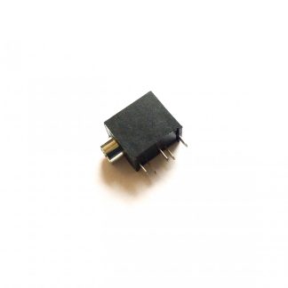
PJ-325 3.5mm Headphone Jack
Add to cart -
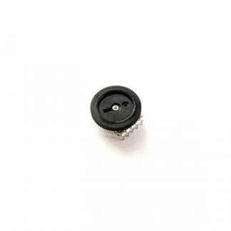
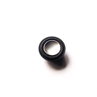
B103 Volume Wheel 10K Ohm 5Pin Double Dial Taper
Read more -
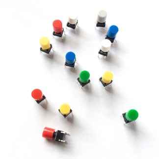
Momentary Push Button Tactile Switches with Caps (2pcs, 6x6x10mm)
Select options This product has multiple variants. The options may be chosen on the product page -
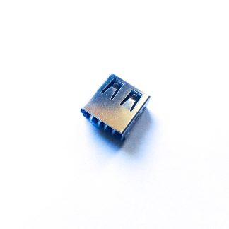
USB Female Type A 4-Pin Socket/Port
Add to cart -
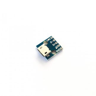
Micro USB micro-B Breakout Board
Add to cart
Is the audio that bad? and where i can get that filter? and if u can give me link to it on aliexpress. (Easy to order from aliexpress for me)
Yes and you really need a filter but I don’t think there’s any available low pass filter module alone. You might be interested with my v2.0 board with builtin amp and filter.
i found on sudomod forum some filters build from resistors and capacitors. But can u send me wiring guide how to put that into this schematic for PCB 1.0?
Does it work even if i dont wire the headphone jack?
Yes controller inputs should work even without a headphone jack.
Does this fit in a regular DMG (original gameboy) case?
Yes it’s designed specifically for the DMG case.
Does this work with the DPI Adapter?
No as this controller board is intended for a GPIO oriented setup.
How does pw1 and pep differ from the 5v outputs? I have wiring set up to power my raspberry pi directly. Rather than using the gpio pins