This method does not use a 40-pin header pins but it’s easier. Place the Pi Zero on top of the DPI Adapter and align the holes. Use a binder clip to hold them together.
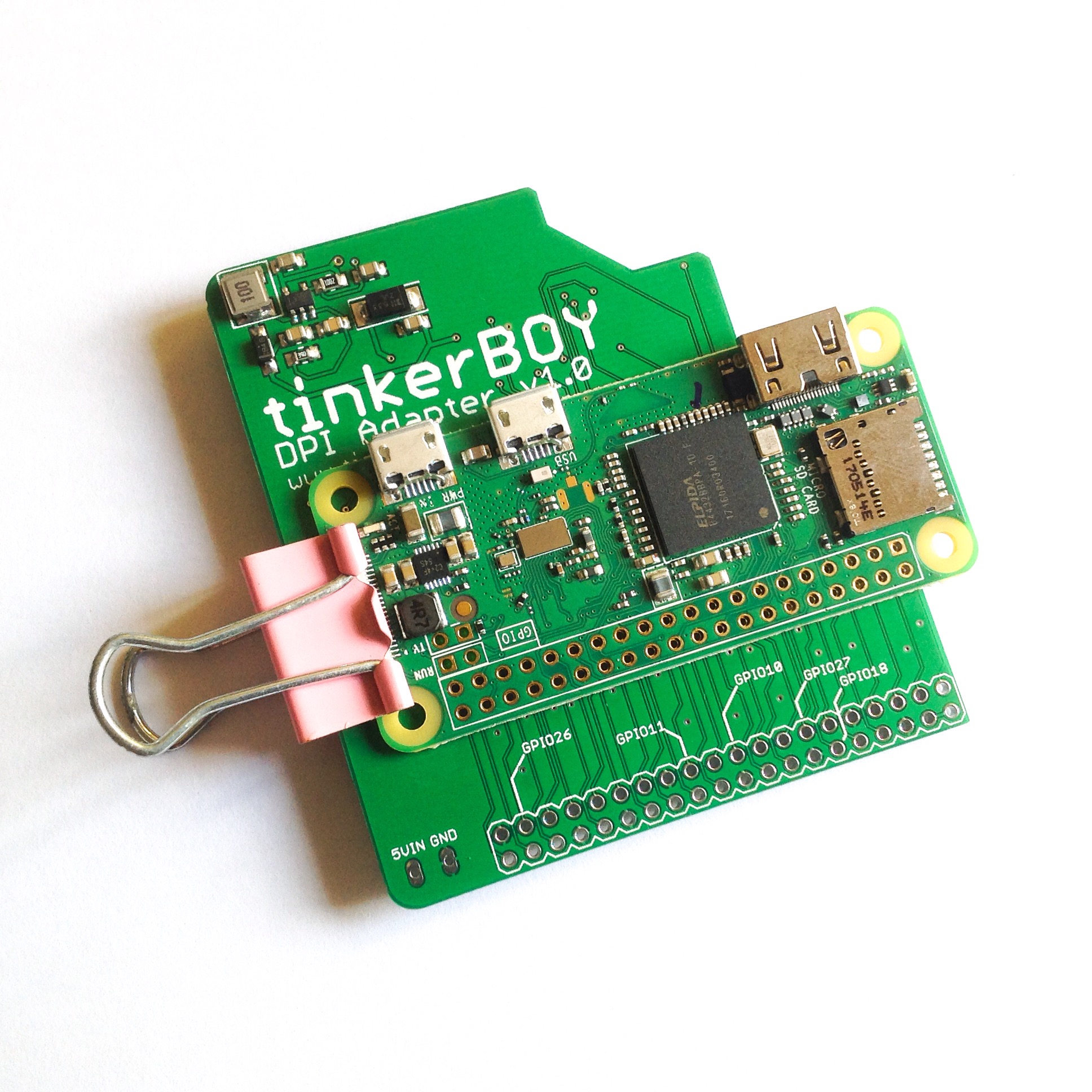
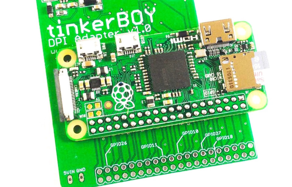
Now, start soldering each of the Pi Zero’s GPIO holes making sure there’s a proper contact to each of the holes on the DPI Adapter.
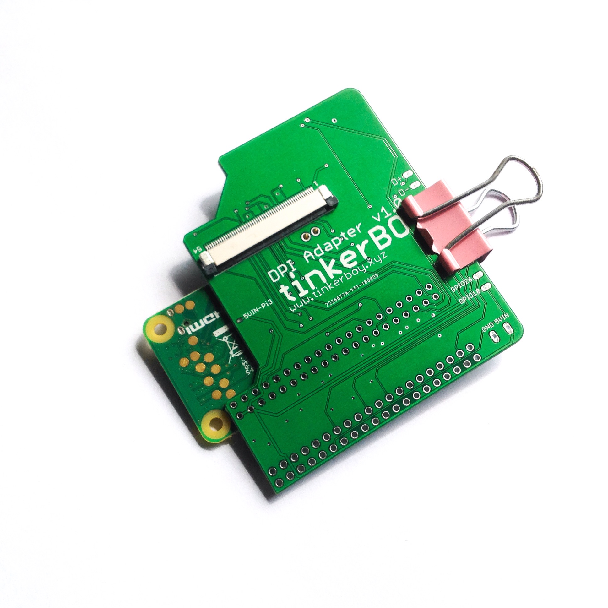
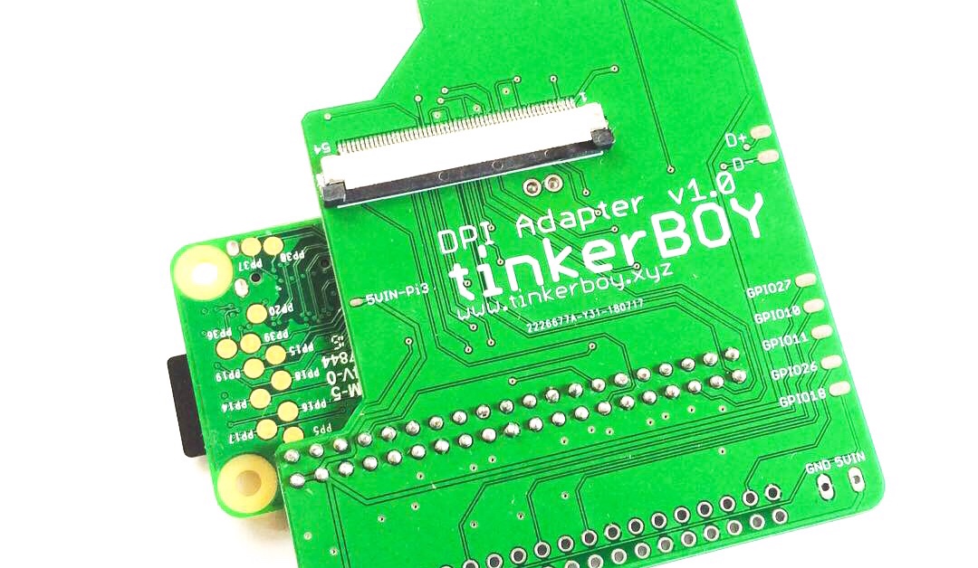
You can also solder from the bottom just to make sure each holes are soldered properly.
The final step is to solder the Pi Zero’s USB data pins (D+ and D-) to the 2 holes on the DPI Adapter. These holes will connect the Pi Zero’s data pins to the D+ and D- pads on the adapter for connecting any USB device. (Note: The D+ and D- pads on the DPI board V1.0 are mislabeled. The upper pad should be D- and the lower pad should be D+. Thanks to Paul for reporting.)
UPDATE: The D+ and D- data pins are now correctly labeled on v1.1 and moved to front left of the board just above the 5v and GND pin holes.
The 5VIN and GND pin holes below the tinkerBOY DPI Adapter are your 5v and GND inputs.
[…] tinkerBOY DPI Adapter v1.0: Visual Guide for Raspberry Pi Zero (without header pins) – RECOMMENDED METHOD […]
This method appears to be way better, unfortunately for me it is too late for the DPI board and my RPi Z as they were both destroyed by following the original method. Maybe in the future I will try again. Thank you for responding to my comment and posting this updated guide for other to use.
Contact me and i will give you a discount if you want to try it again.
Hello Tinkerboy, just a quick question please. I’m building my first GBZ using PI zero+Controller3.0+DPI adaptor. For the step: “The final step is to solder the Pi Zero’s USB data pins (D+ and D-) to the 2 holes on the DPI Adapter”. I thought the D+ and D- of DPI adapter would go to the controller 3.0 (D+ and D-). Please let me know if that is not the case (probably why my gamepad is not recognized). Sorry if this is a obvius question, but I’m new on this type of building. Apreciate any comment/guidance. Thank you.
You have to solder the two holes from the dpi adapter to the pi zero’s data pins so you can connect/solder the v3 to the dpi adapter’s d+ and D-.
Remember the D+ from the dpi adapter goes to the D- on the v3 and the D- from the dpi adapter goes to the D+ on the v3.
You can also directly connect the v3 to the pi zero ‘s microusb port with a stripped microusb cable.
im confused by this too. are there two separate sets of data connectors on this adapter? if so where are they and which goes to which. All I see are the two pads labeled D+ and D-. sorry if this is a dumb question but I am very new to this.
hey tinkerboy, just got my dpi adapter and my v3 board today, what wires go from the v3 board to the dpi board/pizero? thanks in advance!
From the v3 connect D+ to D- on DPi and D- to D+ on DPI.
Must the Pi Zero be connected to the upper row of GPIO holes on the DPI board, or can it also be connected to the lower row (which I imagine is for the Pi 3)? I don’t see an unobstructed view of the traces in the photos, so I can’t be sure.
The reason I’d like to put it lower is to get the microSD card away from the contrast opening in the case. I have my micro USB charging port in that contrast opening, the power LED in the round charging port, and the SD card routed through the cartridge adaptor into a custom cartridge for easier access and a cleaner look on the left side of the case.
I suppose my alternative is to use wires to connect the two, but soldering it to the lower connector would be much cleaner and easier, if it is possible.
Yes you can do it but the two holes on the dpi adapter will not align to the Pi Zero’s data pins. Which means you just need to directly connect any USB device, if you’re going to use one, to the Pi Zero’s micro USB port. You also need to power the Pi Zero separately.
With all due respect, I can’t for the life of me figure out why you recommend this method over the header pins method. I ruined my Pi Zero and the DPI adapter because my board went crooked while soldering and in trying to desolder them I ruined both boards. The header pin method at least ensures the boards are aligned, you can clip the excess after soldering.
Hi, I have this adapter with a pi zero build and i’m thinking about to upgrade my build with a pi zero 2 but i don’t know if this board will be compatible with the zero 2. Have you tested it?
Thanks!