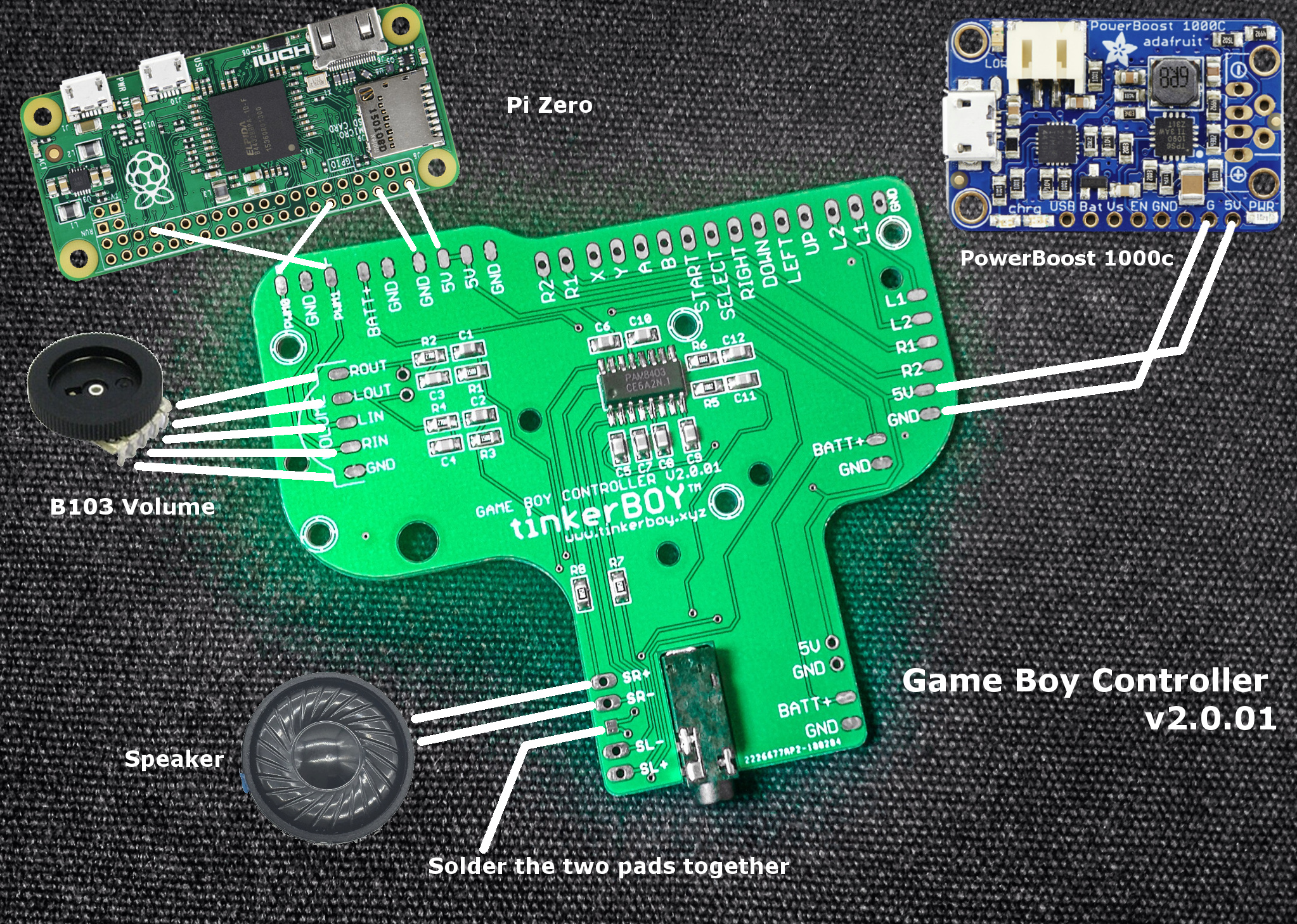
Here’s a visual guide on how to wire the Game Boy Controller v2.0.
Latest version v2.0.01:
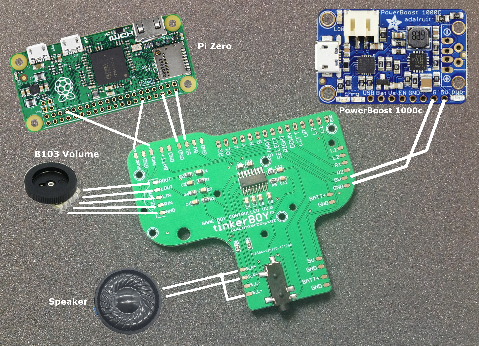
Previous version: v2.0:
Additional Parts You May Need:
-
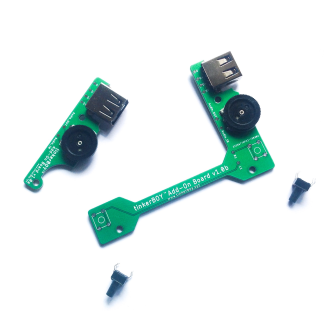
tinkerBOY Add-On Board – with Pre-soldered USB Type A Port and 3-Pin Volume Wheel, Back Buttons
Select options This product has multiple variants. The options may be chosen on the product page -
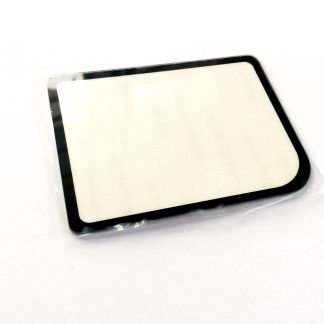
Game Boy Zero Glass Screen Cover Protector
Select options This product has multiple variants. The options may be chosen on the product page -
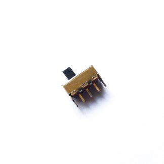
SPDT Slide Switch 1P2T for Game Boy Zero
Add to cart -
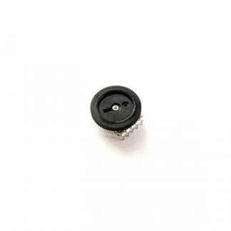
B103 Volume Wheel 10K Ohm 5Pin Double Dial Taper
Read more -
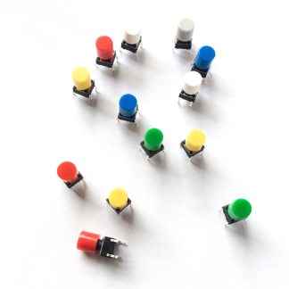
Momentary Push Button Tactile Switches with Caps (2pcs, 6x6x10mm)
Select options This product has multiple variants. The options may be chosen on the product page -
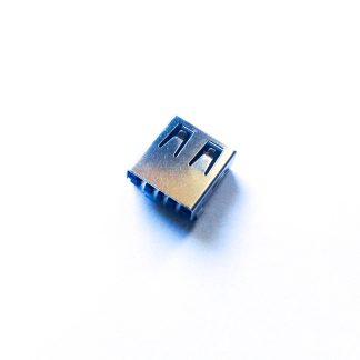
USB Female Type A 4-Pin Socket/Port
Add to cart -
Micro USB micro-B Breakout Board
Add to cart
Hello
If I hook it up exactly like this I don’t have to use all the controller hooks up?
You need the controller buttons of course. :). I will be adding some pictures here soon for wiring the buttons via GPIO or Pro Micro.
I can’t get the volume wheel working. Are these actually getting GPIO pins assigned to them from the Pi Zero?