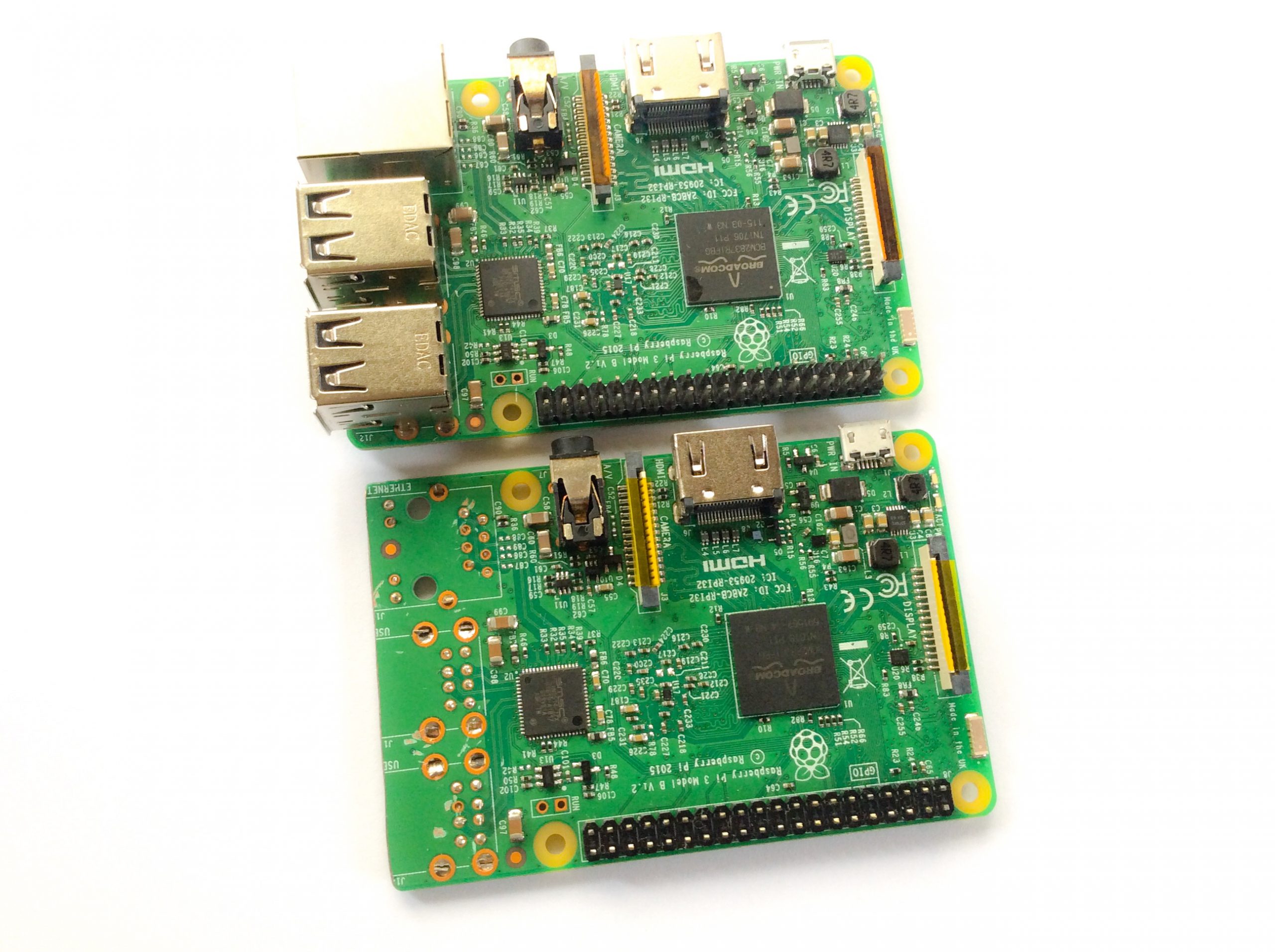
Start by removing the USB ports and ethernet port, cut the header pins, and trim the side of the P1 3 board where you removed the ports.
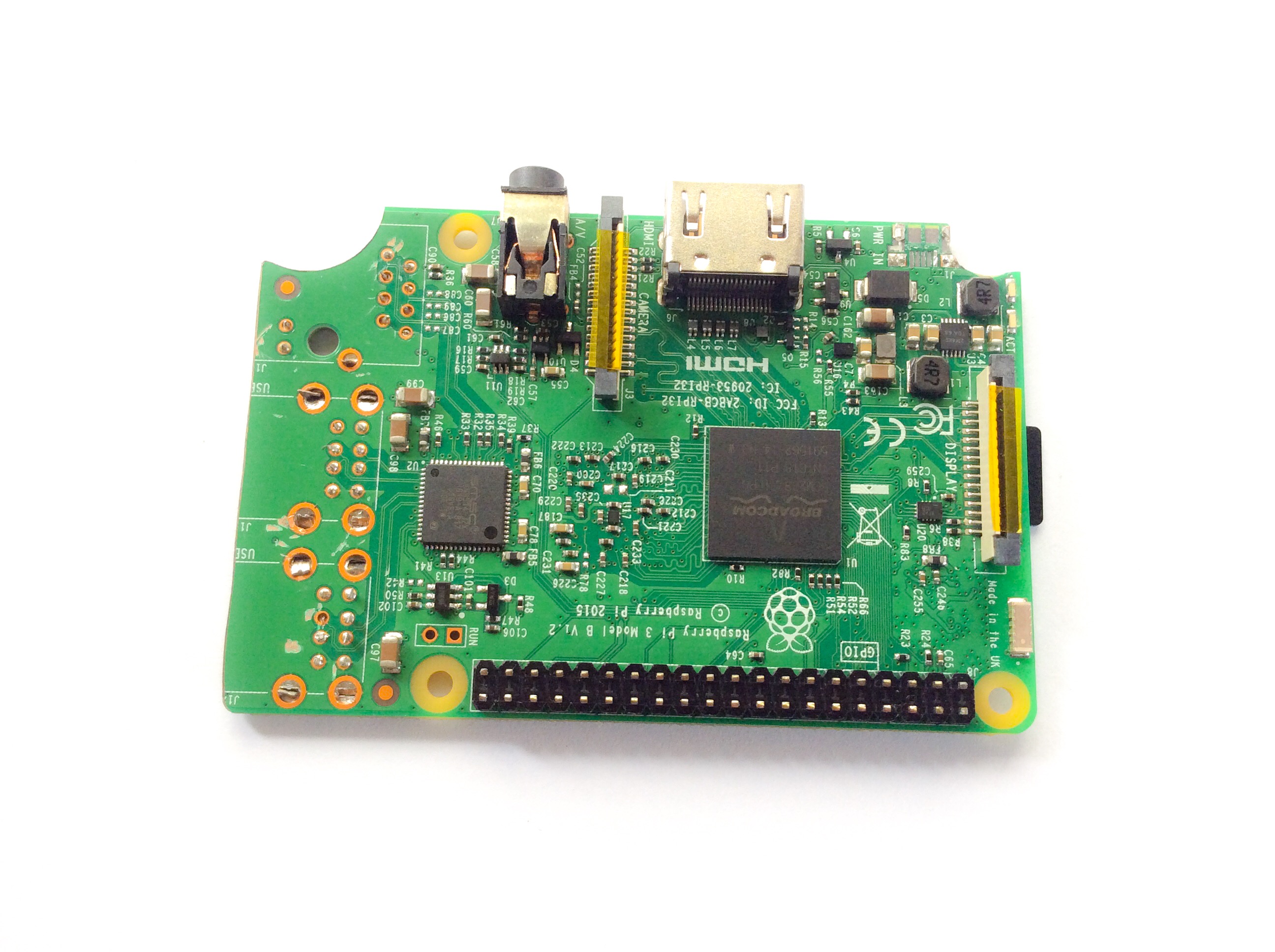
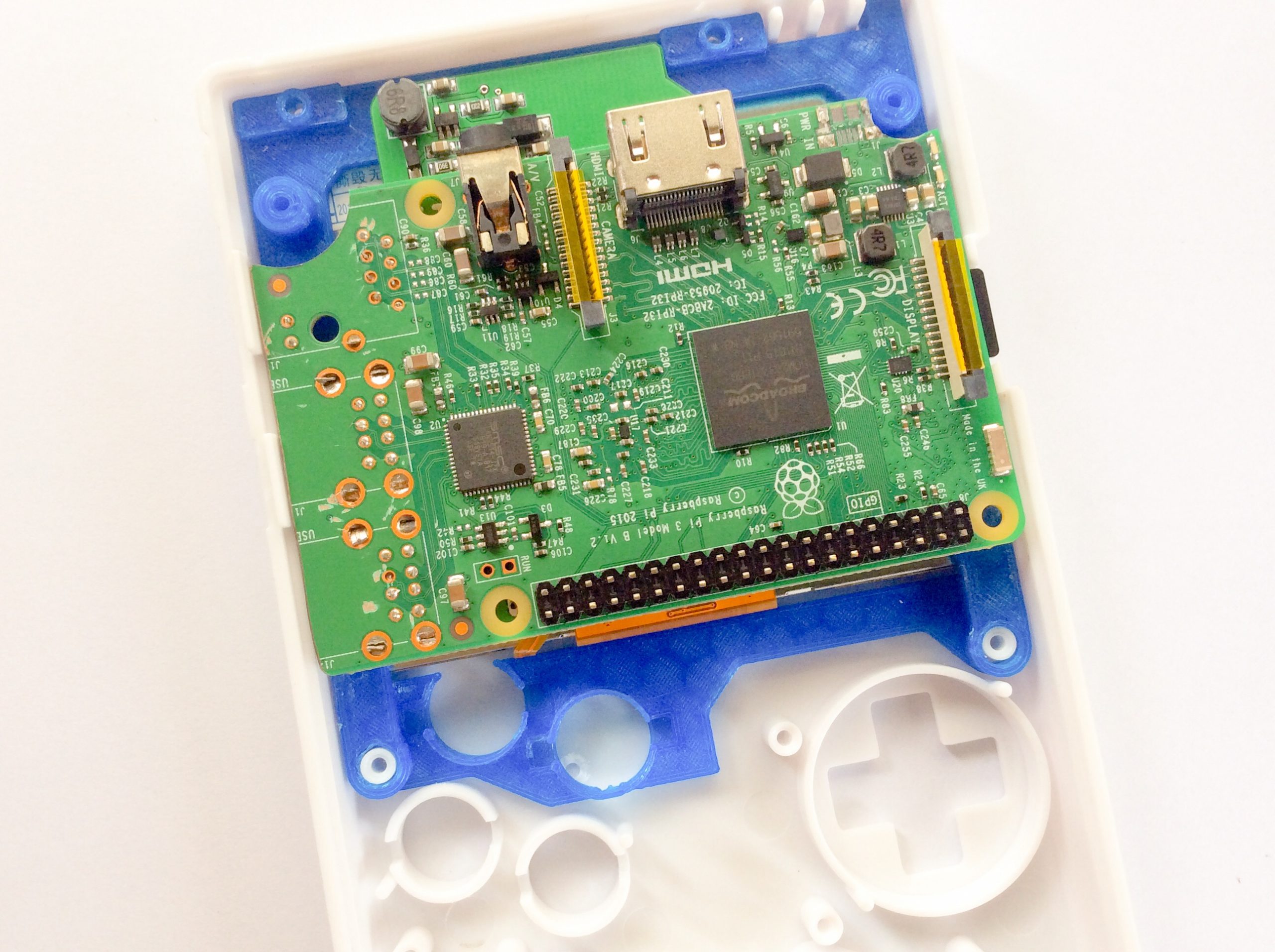
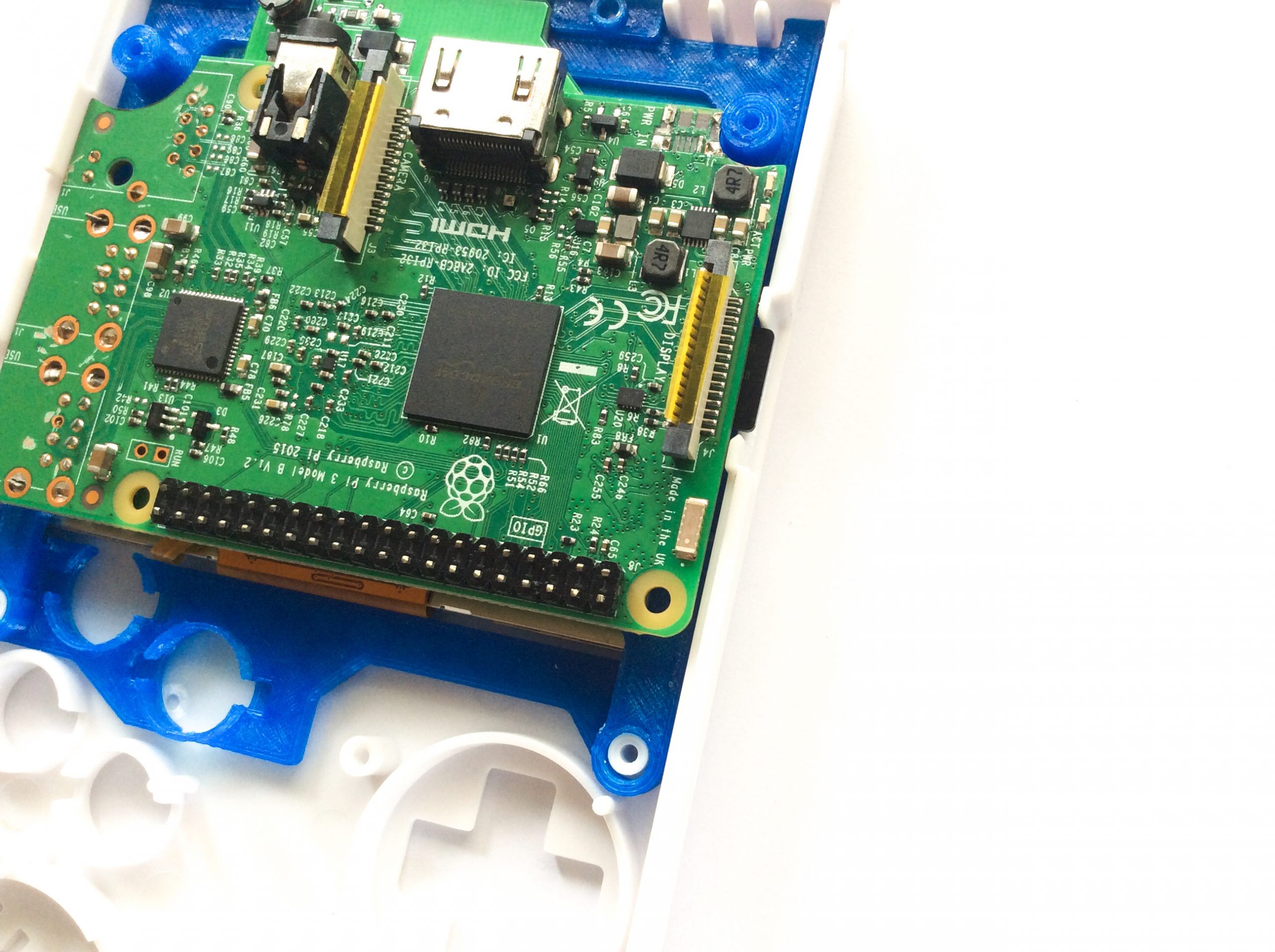
The idea is to mount the Pi 3 inside the Game Boy DMG case so that the sdcard is accessible via the “CONTRAST” area of the case. Use any rotary tool to trim the upper corners to make space for the 3d printed bracket’s top screw posts so you can easily mount it later inside the case.
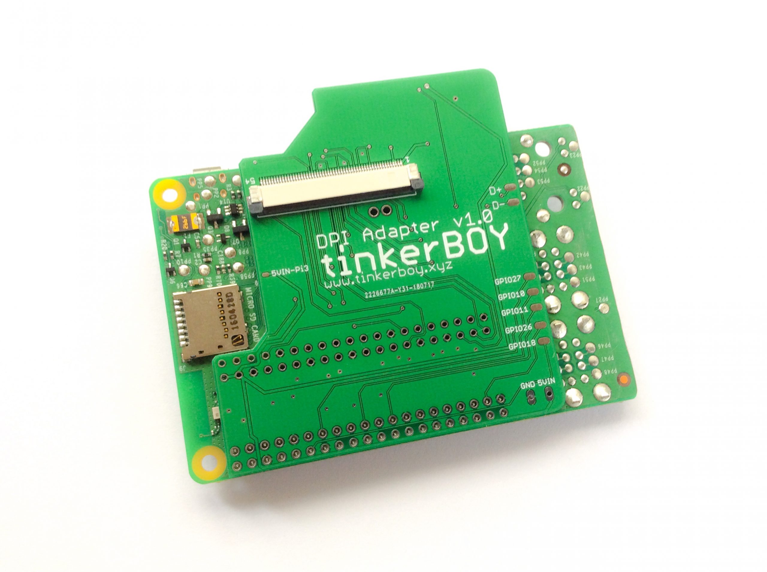
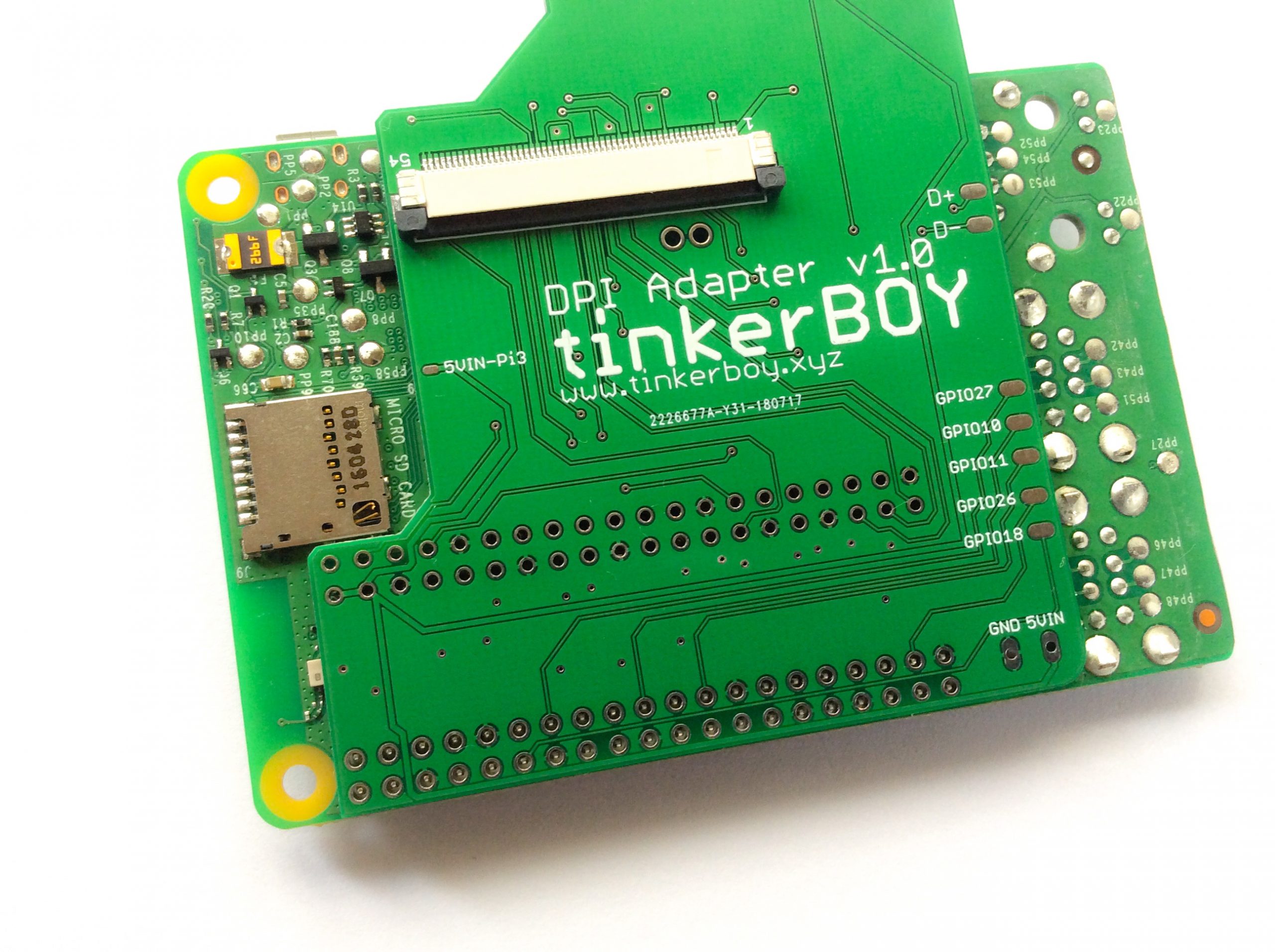
Before joining the adapter and Pi 3 together make sure you put any protection like kapton tape in between to avoid shorts. Solder the pin holes from the adapter where the bottom GPIO pins of the Pi 3 are located. Unlike the Pi Zero which can be powered directly from the GPIO pins, the Pi 3 is protected by a fuse so it’s recommended to power it via the PP2(5v+) and PP5(GND) pin. Here’s how you do it.
This how it looks inside the Game Boy DMG case:
The 5VIN and GND pin holes below the tinkerBOY DPI Adapter are your 5v and GND inputs.
[…] tinkerBOY DPI Adapter v1.0: Visual Guide for Raspberry Pi 3 […]
Hello,
Do you know where I can find the bracket 3d model to print it?
Or where I can buy it ?
Best regards,
Hi, you can look on eBay, I found it there and it’s pretty cheap, just type Gameboy zero bracket or something like that, you’ll see there.
I received the board and have one question. What are the GPIO pins on the DPI Board for? I mean the ones on the right side, below the D+/D-?
Is it for using a shutdown circuit? Is it possible to use these circuits with the DPI using the complete GPIO head?
You can use those available GPIO pins for any task you can use them for.
Am I able to use this method to run this display on the newer model A+?
Yes it’s compatible with Pi 3 Model A+ and B+.
If i use the dpi board with b3+, does D+ & D- on the dpi board still useable? I try once and i cannot use my button.
No, the D+ and D- pins on the dpi adapter are for the Pi zero only. Just directly solder the data pins to the Pi 3B+.
Do you need to solder all the pins on the underside of the pi3 to this board? Are standard GPIO controls compatible with this board? (Or would you need an Arduino or one of your better boards w/ controls?) When you say “GPIO”, are you referring to the actual GPIO number assignment, or just the physical pin number?
Yes you need to solder all the pi3 header pins. You need a usb based controller like my v3 to go with the dpi adapter. Yes GPIO Number assignment.
Would the v2.2 board work with it?
If I understand correctly, the PSU goes on the tinkerboy DPI adapter 5Vin and GND. Then I connect the 5Vin-pi3 to pp2. I don’t connect pp5. Am I right?
For Pi3 it’s better if you power it directly from the PSU.
So i dont use the 5Vin-pi3 on your board ?